
Active anti-floating design method based on anti-floating variable water level

A design method and water level variable technology, applied in design optimization/simulation, infrastructure engineering, special data processing applications, etc., can solve problems such as increased construction costs, economic losses, poor groundwater runoff, etc., to achieve low construction costs and efficient construction Simple, technically feasible effect

Pending Publication Date: 2021-12-03
ZHENGYE ENG & INVESTMENT INC
View PDF0 Cites 4 Cited by
  • Summary
  • Abstract
  • Description
  • Claims
  • Application Information

AI Technical Summary

Problems solved by technology

[0002] With the development and utilization of urban underground space, the original hydrogeological environment of the site is destroyed, and the original runoff conditions of the site are changed and blocked, resulting in poor runoff of surface water such as atmospheric rainfall and groundwater, which infiltrates and collects into the foundation pit, causing groundwater The sudden rise in water level forms a "pool-basin effect". The water level of the "pool-basin effect" belongs to the abnormally unstable water level of the construction site, which is accidental and destructive. It is often ignored in the anti-floating design and construction of buildings, causing huge economic losses and even posed a safety hazard to the building
On the one hand, it shows that the surrounding surface waterproof and drainage system has not been perfected during the construction period, and the anti-floating structure has not yet been completed. Damage to the building structure during construction, on the other hand, if the impact of the "pool-basin effect" has not been considered in the anti-floating design or the anti-floating safety reserve capacity is not enough to resist the water buoyancy of the "pool-basin effect", it will cause damage to the building structure during the operation period. Moreover, if the anti-floating design is carried out according to the water level of the "pool effect" in the anti-floating design, the construction cost will increase significantly.

Method used


Image

  • Active anti-floating design method based on anti-floating variable water level
  • Active anti-floating design method based on anti-floating variable water level
  • Active anti-floating design method based on anti-floating variable water level

Examples


Embodiment 1

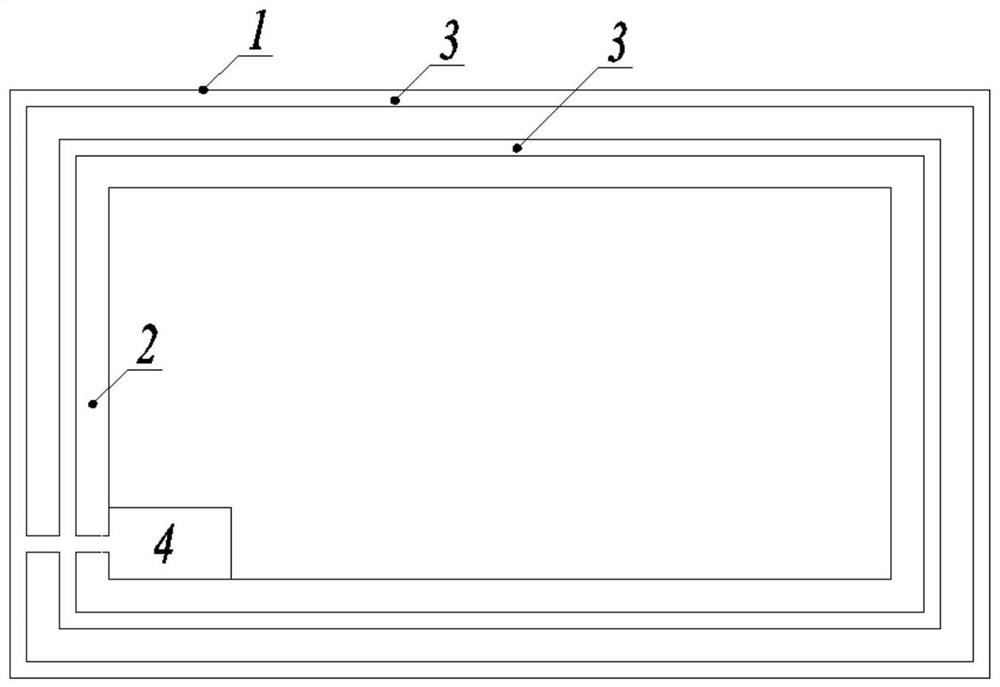
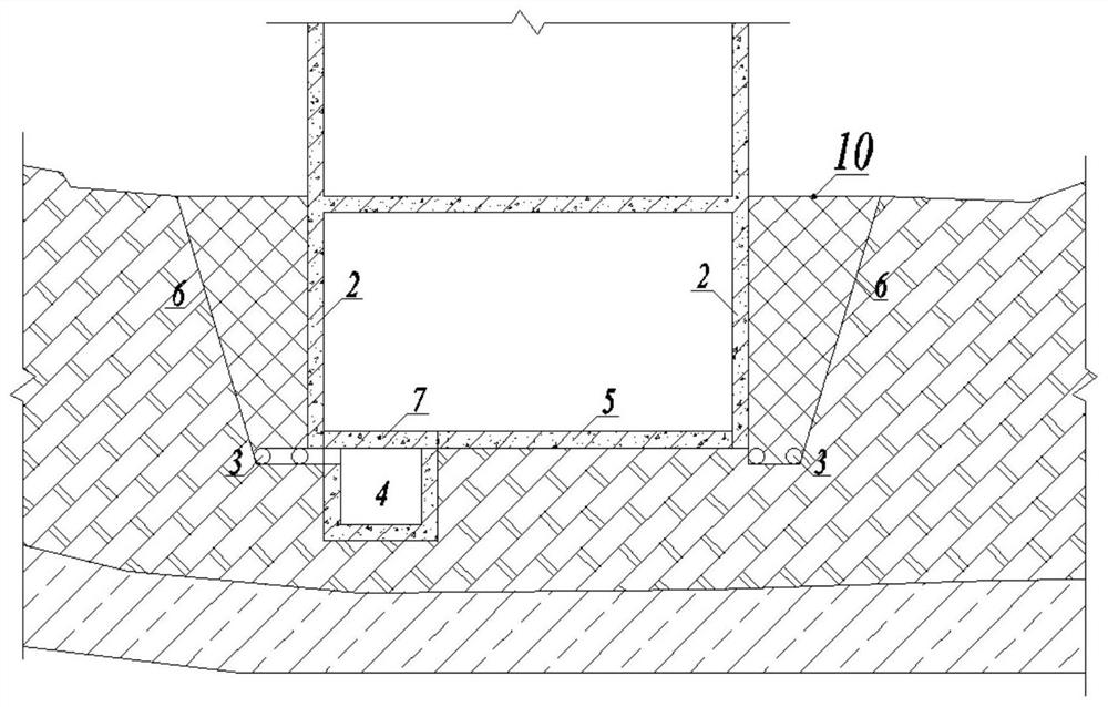
[0035] An active anti-floating design method based on anti-floating water level is suitable for such as figure 1 and figure 2 As shown in the drainage layout, after the excavation of the foundation pit is completed, the water collection well 4 will be built, and the reinforced concrete cover plate 7 will be installed in the water collection well. The drainage pipe 3 is arranged between them and its position is fixed. The drainage pipe 3 is connected with the water collection well 4, and the collected water in the water collection well 4 is discharged out of the basement through the pumping and drainage equipment; the basement floor 5 and the basement exterior wall 2 are poured, and finally the basement exterior wall 2 The foundation pit fertilizer groove between the foundation pit side wall 6 to the ground 10.

[0036] like Figure 5 As shown, the specific implementation process is as follows:

[0037] In step 1, when the underground water level of the construction site ri...

Embodiment 2

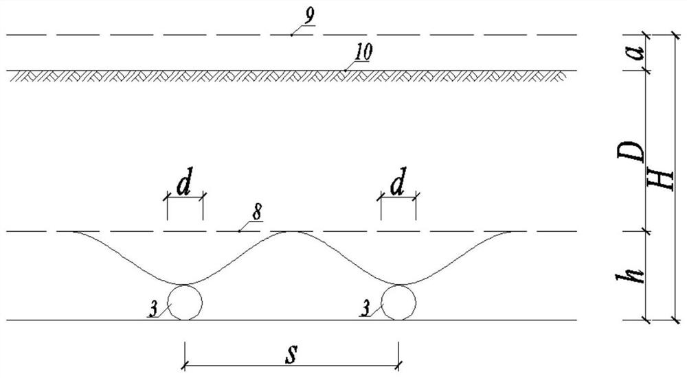
[0067] Step 1: Taking the bottom of the buried pipe as the benchmark, consider that the elevation of the anti-floating water level is H=26m, the anti-floating constant water level is h=5m, the seepage flow path D=20m, and the head difference Δh between the anti-floating water level and the anti-floating constant water level =21m, the width B of the fertilizer groove of the foundation pit at the constant water level against buoyancy 1 =5m, single pipe burial length (length of foundation pit) L=500m, soil permeability coefficient k=0.1m / s.

[0068] Substituting the parameters into formula 1.1 to obtain the hydraulic gradient between the anti-floating water level and the anti-floating constant water level:

[0069] Substitute the parameters into formula 1.2 to obtain the cross-sectional area at the constant water level: A 1 =B 1 L=5×500=2500m 2

[0070] Substitute the parameters into formula 1.3 to obtain the permeation flow at the constant water level against buoyancy: Q=k...


PUM


Abstract

The invention provides an active anti-floating design method based on an anti-floating variable water level. The method comprises the following steps: calculating the total precipitation amount Q of the anti-floating variable water level according to the soil permeability, the anti-floating highest variable water level, the anti-floating constant water level, the width of a foundation pit fat groove at the anti-floating constant water level, the embedding length of a single pipe and a seepage flow path; uniformly burying pipes at the bottom of the foundation pit fat groove, and calculating the anti-floating variable water level precipitation component qd borne by a single pipe according to a uniform spreading method; assuming that the flow flowing to the drainage pipe can penetrate through the pipe wall and is discharged by the drainage pipe, calculating the water inflow qj of the single pipe according to an averaging method; calculating the number n of buried pipes according to a drainage pipe water inlet capacity checking calculation formula; and calculating the pipe laying spacing s according to the bottom width of the foundation pit fat groove. According to the method, building structure damage caused by imperfect water prevention and drainage of the peripheral earth surface in the construction period and the 'basin effect' when the self weight of the building is still small is avoided, and building structure damage caused by lack of effective water prevention and drainage measures or insufficient anti-floating safety reserve to resist the 'basin effect' water buoyancy in the operation and maintenance period is also avoided.

Description

technical field [0001] The invention relates to an active anti-floating design method based on the anti-floating variable water level, and belongs to the technical field of building anti-floating technology. Background technique [0002] With the development and utilization of urban underground space, the original hydrogeological environment of the site is destroyed, and the original runoff conditions of the site are changed and blocked, resulting in poor runoff of surface water such as atmospheric rainfall and groundwater, which infiltrates and collects into the foundation pit, causing groundwater The sudden rise in water level forms a "pool-basin effect". The water level of the "pool-basin effect" belongs to the abnormally unstable water level of the construction site, which is accidental and destructive. It is often ignored in the anti-floating design and construction of buildings, causing huge economic losses and even lead to building safety hazards. On the one hand, it...

Claims


Application Information

Patent Timeline
Patent Type & Authority Applications(China)
IPC IPC(8): G06F30/13G06F30/20E02D31/12G06F119/14
CPCG06F30/13G06F30/20E02D31/12G06F2119/14
Inventor 沈志平谢涛付君宜彭又贤刘慧孙秀东尹林莉
Owner ZHENGYE ENG & INVESTMENT INC
Learn More