
Revolving body scanning measurement method and data compensation calibration method thereof

A technology of data compensation and calibration method, applied in the field of laser scanning, can solve the problems of high work intensity, low efficiency, large errors, etc., and achieve the effect of reducing data, ensuring data, and reducing scanning errors

Pending Publication Date: 2021-12-03
RES INST OF ZHEJIANG UNIV TAIZHOU
View PDF0 Cites 0 Cited by
  • Summary
  • Abstract
  • Description
  • Claims
  • Application Information

AI Technical Summary

Problems solved by technology

In the traditional method, the manual detection method is used, which has high work intensity, low efficiency, and large errors. Therefore, a detection equipment that can efficiently and accurately measure the dimensional parameters of the rotating body is needed.

Method used


Image

  • Revolving body scanning measurement method and data compensation calibration method thereof
  • Revolving body scanning measurement method and data compensation calibration method thereof
  • Revolving body scanning measurement method and data compensation calibration method thereof

Examples


Embodiment 1

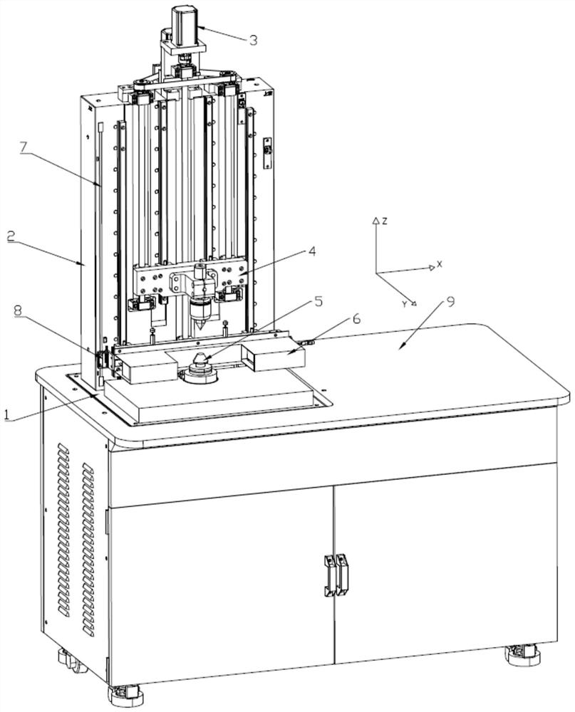
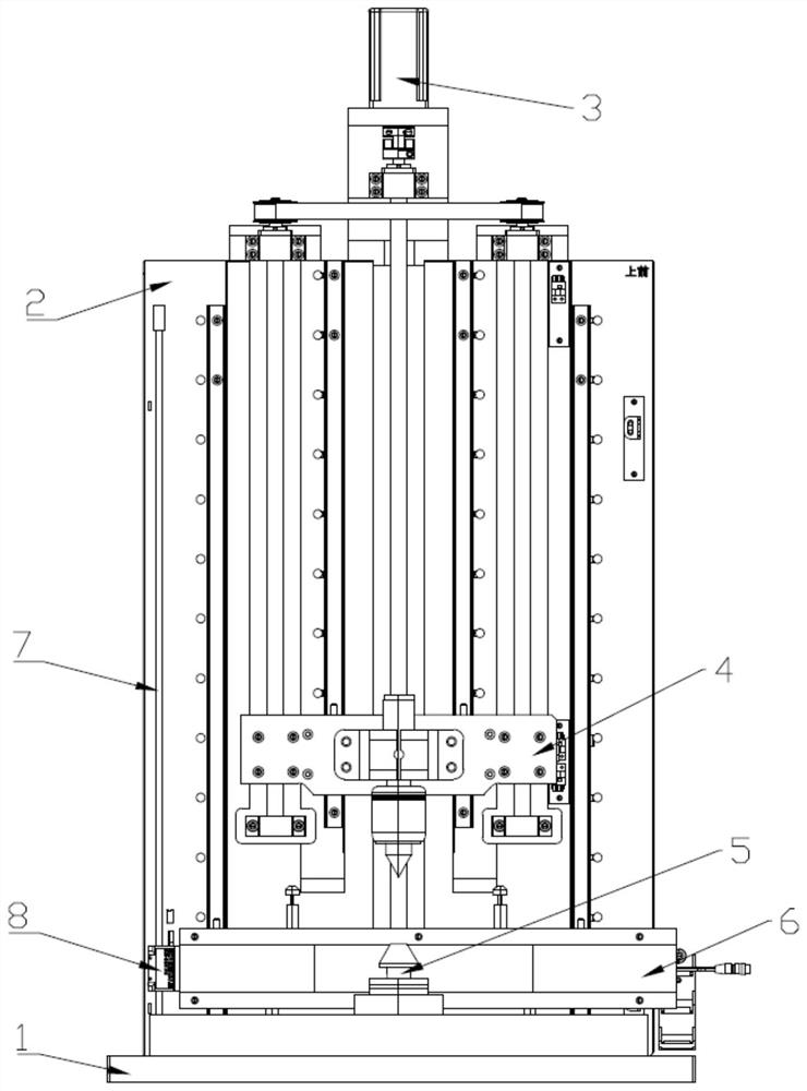
[0084] Such as figure 1 , 2 As shown, a high-precision rotating body measuring device includes a data processing device, a fixed table, a moving device 3, a positioning assembly, a scanning device 6 and a distance measuring device, wherein the moving device 3 is arranged on the fixed table; the positioning assembly is divided into two parts Parts are respectively arranged on the moving device 3 and the fixed platform, the positioning assembly is used to fix the revolving body; the scanning device 6 is arranged on the moving device 3; the distance measuring device is arranged on the fixed platform, and the distance measuring device is used to detect the scanning device 6 Traveling distance; the processing device is respectively connected to the distance measuring device, the moving device 3 and the scanning device 6 through communication.

[0085] The fixed platform includes a base 1 and a stand 2, the stand 2 is vertically arranged on the base 1, and the stand 2 is a square m...

Embodiment 2

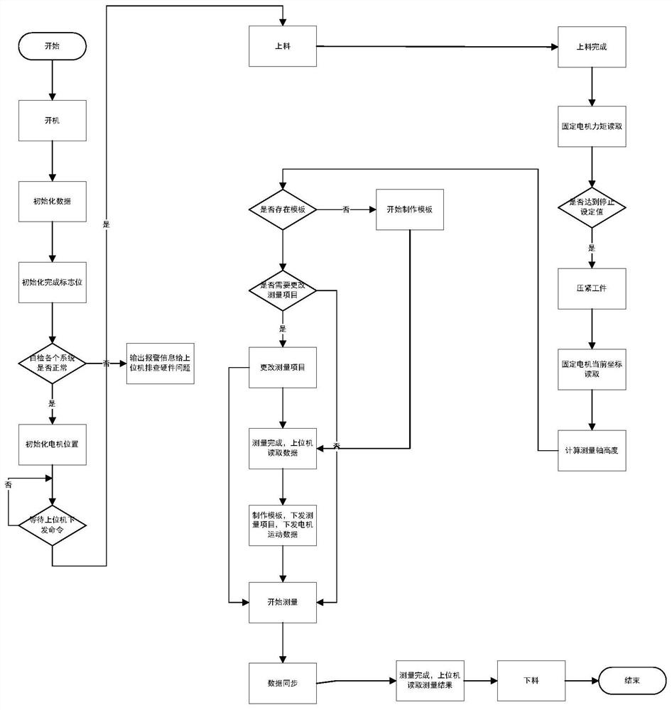
[0189] This embodiment is obtained based on Embodiment 1, wherein the relative position of the upper positioning cone and the lower positioning cone needs to be tilted and self-calibrated before step 1; the tilted self-calibration includes the following steps:

[0190] Step S1: The data processing device receives the corresponding instruction and enters the tilt self-calibration mode;

[0191] Step S2: The scanning device scans the standard calibration rod, combined with the distance measuring device, to obtain scanning data; the standard calibration rod is a rotating body with known shaft diameter and height data;

[0192] Step S3: The data processing device obtains the inclination angle α of the standard calibration rod in the Y-Z plane according to the scan data;

[0193] Step S4: Obtain the inclination angle β of the standard calibration rod in the X-Z plane according to the inclination angle α;

[0194] Step S5: Determine the relationship between the inclination angle α ...


PUM


Abstract

The invention provides a revolving body scanning measurement method and a data compensation calibration method thereof, whether an upper positioning cone and a lower positioning cone are aligned or not is checked through inclination self-correction, and if not, automatic correction is carried out, so that the scanning error is reduced, and the accuracy of scanning data is ensured; slope compensation and system error compensation are carried out on scanning data, and fine tilt errors and system errors are automatically compensated, so that the accuracy of the data is further ensured.

Description

technical field [0001] The invention relates to the field of laser scanning, in particular to a scanning measurement method of a rotating body and a data compensation and calibration method thereof. Background technique [0002] With the development of the motor industry, various types of crankshafts are required. Since the crankshaft needs to rotate at a high speed, the precision of the crankshaft is extremely high. The accuracy of the crankshaft directly affects the operation of the equipment, including the life of the equipment and the noise of the equipment running. In the traditional method, the manual detection method is used, which has high work intensity, low efficiency, and large error. Therefore, a detection device that can efficiently and accurately measure the dimensional parameters of the rotating body is needed. Contents of the invention [0003] The purpose of the present invention is to solve the deficiencies of the prior art, and provide a scanning measur...

Claims


Application Information

Patent Timeline
IPC IPC(8): G01B11/02G01B11/14
CPCG01B11/02G01B11/14G01B21/042
Inventor 陈一信叶雪旺陈浙泊林建宇陈龙威张一航余建安潘凌锋陈逸宸
Owner RES INST OF ZHEJIANG UNIV TAIZHOU
Learn More