
Mixed cooling flame tube used for low-pollution gas turbine

A gas turbine, mixed cooling technology, applied in the combustion chamber, combustion method, combustion equipment and other directions, can solve the problems of reducing the outlet temperature of the combustion chamber, unstable tempering and combustion, easy over-temperature of the wall, etc., to reduce NOx pollutants, The effect of reducing the average outlet temperature and improving the cooling effect

Active Publication Date: 2021-12-03
成都中科翼能科技有限公司
View PDF16 Cites 2 Cited by
  • Summary
  • Abstract
  • Description
  • Claims
  • Application Information

AI Technical Summary

Problems solved by technology

[0006] Among them, the problem brought by Article 1 is: tempering and combustion instability
[0007] The problem brought by article 2 is: it is difficult to cool the head of the flame tube, and the wall is easy to overheat
[0010] Take this patent as an example. This is a low-pollution combustion chamber design. It uses the airflow channel formed between the outer casing of the flame tube and the flame tube to cool the wall of the flame tube. However, the heat transfer efficiency of this convection cooling method is very low. , it is difficult to really make the wall reach a reasonable temperature
The second problem is that a number of mixing holes are distributed at the end of the flame tube, and its function is to reduce the outlet temperature of the combustion chamber to meet the requirements of the turbine inlet. In this way, a large amount of cooling air is supplied into the combustion chamber, which will lead to the generation of a large amount of CO
The third problem is that premixed combustion is very prone to backfire problems, and there are no anti-backfire measures in this patent
[0012] Taking this patent as an example, this is also a low-pollution combustion chamber design, which focuses on the premixed combustion at the head, effectively reducing NOx emissions, but still uses traditional film cooling, and does not consider the CO generation on the wall
Second, the patent also does not consider the tempering problem

Method used


Image

  • Mixed cooling flame tube used for low-pollution gas turbine
  • Mixed cooling flame tube used for low-pollution gas turbine
  • Mixed cooling flame tube used for low-pollution gas turbine

Examples


Embodiment

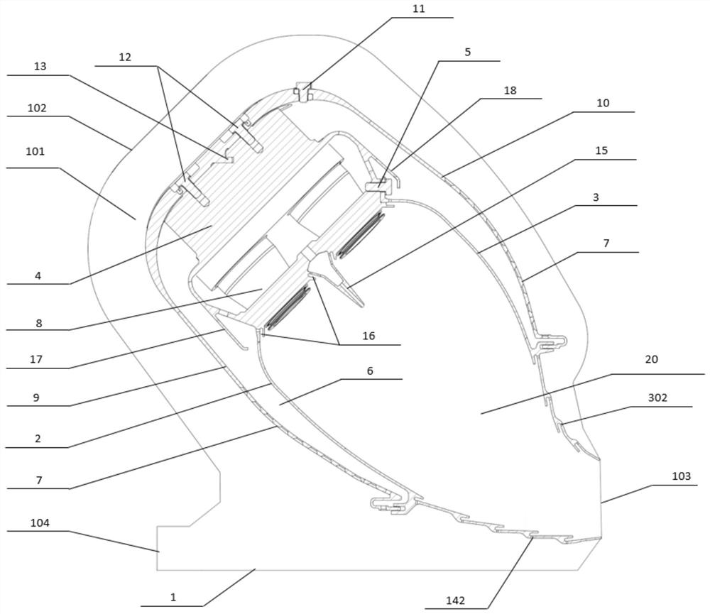
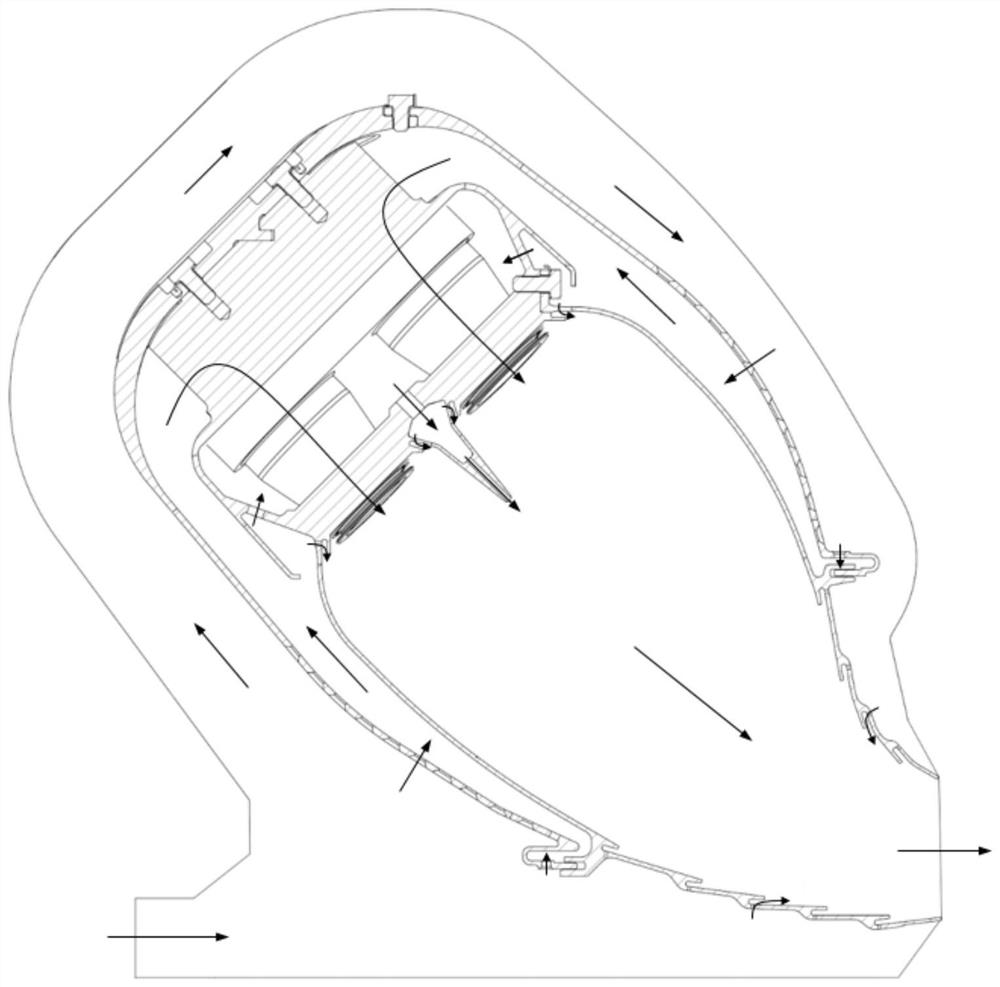
[0037] Such as Figure 1-4As shown, the present embodiment provides a mixed cooling flame cylinder for low-pollution gas turbines, which is arranged in the combustion chamber 1 and includes a fairing, an inner wall 2, an outer wall 3 and a head structure 4, and the fairing is arranged in the combustion chamber 1 A gas circulation channel 101 is formed between the inner wall and the inner wall of the combustion chamber 1; the inner wall 2, the outer wall 3 and the head structure 4 are all installed in the fairing, and the head structure 4 is close to the combustion chamber 1 outside the combustion chamber 102 Set on one side; one end of the inner wall 2 and one end of the outer wall 3 are connected to the head structure 4, the inner wall 2 is arranged on the side close to the combustion chamber inlet 104, and the inner wall 2, the outer wall 3 and the head structure 4 are formed. Inner cavity 20, the end of inner cavity 20 away from head structure 4 is the opening end correspon...


PUM


Abstract

The invention discloses a mixed cooling flame tube used for a low-pollution gas turbine. The mixed cooling flame tube comprises a fairing, an inner wall, an outer wall and a head structure, the fairing is arranged in a combustion chamber, a gas circulation channel is formed between the fairing and the inner wall of the combustion chamber, the head structure is arranged on one side close to the combustion chamber outer corridor; one end of the inner wall and one end of the outer wall are both connected to the head structure, the inner wall is arranged on the side close to a combustion chamber inlet, one end of the fairing is an open end arranged towards an outlet of the combustion chamber, and the middle of the inner wall and the middle of the outer wall are both connected with the open end of the fairing, a plurality of rows of impact holes are distributed in the fairing, and a swirl nozzle is arranged in the head structure. The flame tube is cooled in a sectional mode, the good cooling effect is achieved, and CO pollutants are not prone to exceeding the standard.

Description

technical field [0001] The invention belongs to the technical field of combustion chambers, and in particular relates to a mixed cooling flame cylinder for low-pollution gas turbines. Background technique [0002] Gas turbine is a device with good cleanliness and high efficiency. It has the advantages of small size and low weight. It is widely used in power generation, independent energy system, mechanical drive and other fields. However, during the working process of the gas turbine, pollutants such as nitrogen oxides (NOx), carbon monoxide (CO) and unburned hydrocarbons (UHC) will be produced, which are mainly related to the combustion flame temperature, equivalence ratio, intake pressure and The degree of uniformity of gas and air mixing is related. [0003] In recent years, low-emission combustion technology has developed rapidly, and various new technologies have emerged continuously. A number of low-emission combustion technologies have been developed, and various low...

Claims


Application Information

Patent Timeline
IPC IPC(8): F23R3/58F23R3/12F23R3/28
CPCF23R3/58F23R3/283F23R3/12F23R2900/03043Y02T50/60
Inventor 颜腾冲刘宝琪陈柳君代茂林王龙杨治王梁丞赵汝伟
Owner 成都中科翼能科技有限公司
Learn More