
Magnetic suspension blower with adjustable blade tip clearance and debugging method

A technology of blade tip clearance and blower, which is applied to mechanical equipment, machines/engines, liquid fuel engines, etc., can solve the problems of volute adjustment, the inability of blade tip clearance to meet the requirements, and the inability to adjust the impeller and volute blade tip clearance, etc. To achieve the effect of improving the quality of the blast

Pending Publication Date: 2021-12-03
XINLEI COMPRESSOR CO LTD
View PDF1 Cites 1 Cited by
  • Summary
  • Abstract
  • Description
  • Claims
  • Application Information

AI Technical Summary

Problems solved by technology

[0004] The existing technology has the following disadvantages: the volute of the traditional magnetic levitation blower is directly fixed on the casing, and the casing cannot adjust the position of the volute, that is, the tip clearance between the impeller and the volute cannot be adjusted; when the motor stator Or when parts such as the motor rotor drive the relative displacement between the impeller and the volute due to temperature changes, the tip clearance between the impeller and the volute cannot meet the requirements; thus, the impeller and the volute scrape each other due to the small gap, or Due to the large gap, the efficiency of the flow field is reduced, which leads to a decrease in the efficiency of the blower, which reduces the blowing quality of the magnetic levitation blower.

Method used


Image

  • Magnetic suspension blower with adjustable blade tip clearance and debugging method
  • Magnetic suspension blower with adjustable blade tip clearance and debugging method
  • Magnetic suspension blower with adjustable blade tip clearance and debugging method

Examples


Embodiment 1

[0037] Such as figure 1Shown is a magnetic levitation blower with adjustable tip clearance, which includes a casing 1, a motor shaft 2, a magnetic bearing device 3, a plurality of radial and axial sensors 4, an impeller 5, an axial adjustment block 6 and a volute 7 ; The motor stator 11 is fixedly embedded in the inner hole of the casing 1, and the motor shaft 2 is fixedly provided with a motor rotor 21, and the position of the motor stator 11 corresponds to the position of the motor rotor 21; the impeller 5 is fixed on one end of the motor shaft 2, and the axial adjustment block 6 Fixed on the casing 1, the volute 7 is fixed on the axial adjustment block 6; the volute 7 is provided with a blast channel 71, and the impeller 5 is located in the blast channel 71; the axial adjustment block 6 is made of aluminum alloy, and the axial The adjustment block 6 is provided with a cooling water channel 61 and a resistance wire 62; the water inlet end and the water outlet end of the coo...


PUM


Abstract

The invention relates to the field of magnetic suspension air blowers, in particular to a magnetic suspension blower with an adjustable blade tip clearance and a debugging method. The blower comprises a machine shell, a motor shaft, a magnetic bearing device, a plurality of radial and axial sensors, an impeller, an axial adjusting block and a volute; the axial adjusting block is fixed to the machine shell, and the volute is fixed to the axial adjusting block; the volute is provided with an air blowing channel, and the impeller is located in the air blowing channel; the axial adjusting block is made of an aluminum alloy material and is provided with a cooling water channel and a resistance wire; the water inlet end and the water outlet end of the cooling water channel are used for being communicated with a water inlet device and a water outlet device correspondingly, and the resistance wire is used for heating the axial adjusting block; and the air inlet end and the air outlet end of the air blowing channel are provided with a differential pressure flowmeter and a pressure gauge respectively, and the differential pressure flowmeter and the pressure gauge are used for detecting the air flow of the air inlet end of the air blowing channel and the air pressure of the air outlet end of the air blowing channel respectively. The blower can dynamically adjust the blade top gap, and the blowing quality of the magnetic suspension blower is improved.

Description

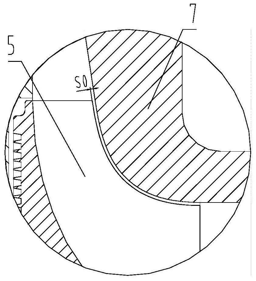
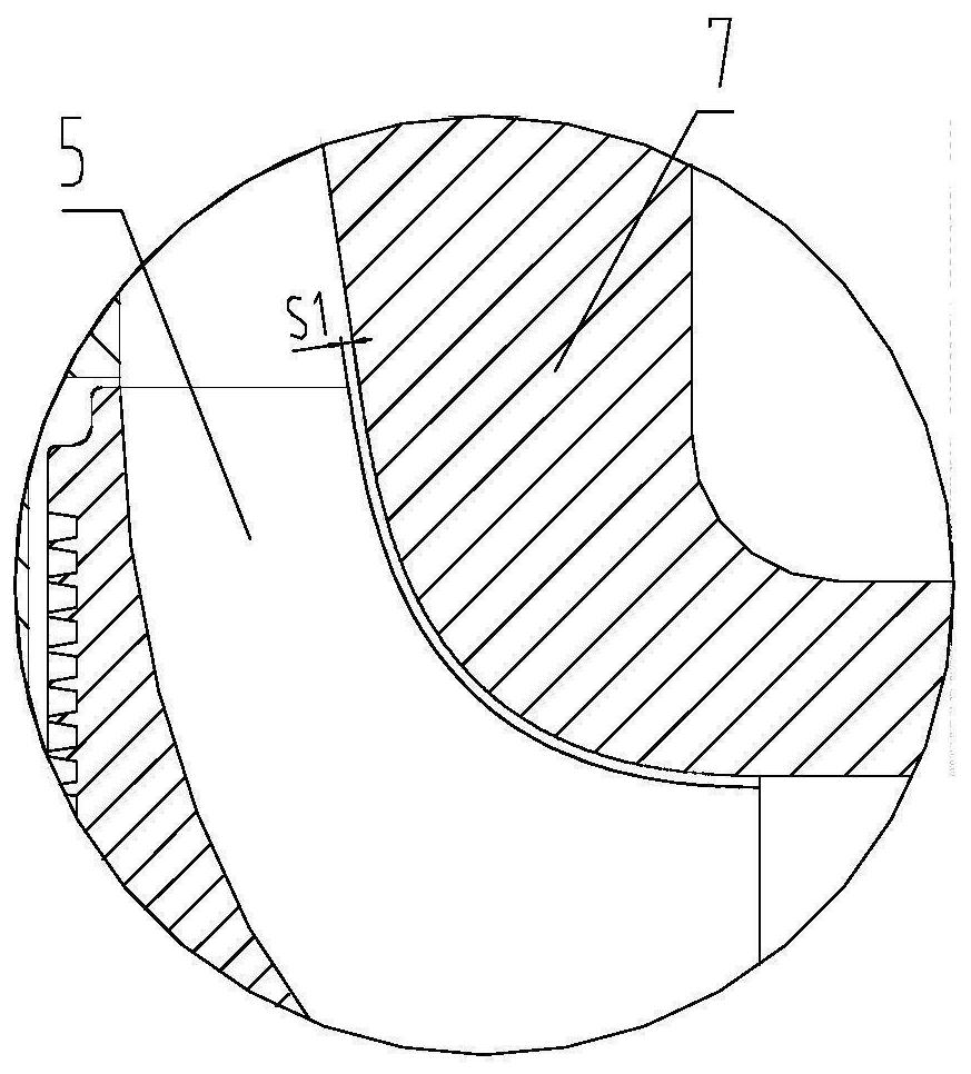
technical field [0001] The invention relates to the field of magnetic levitation blowers, in particular to a magnetic levitation blower with adjustable tip clearance and a debugging method. Background technique [0002] Blower blade tip clearance has always been an important factor affecting blower efficiency and safety. Such as figure 2 , image 3 As shown, the allowable design range of the design blade tip clearance is S0, when the relative displacement of the stator and rotor of the motor due to temperature rise and deformation, the real blade tip clearance can be S1; if the elongation of the rotor is greater than the elongation of the stator, the impeller and worm If the real tip clearance S1 of the shell is smaller than the allowable design range S0, the impeller and the volute may scrape each other, which will cause safety hazards; If the top clearance S1 is greater than the allowable design range S0, the efficiency of the flow field will decrease, resulting in a de...

Claims


Application Information

Patent Timeline
Patent Type & Authority Applications(China)
IPC IPC(8): F04D25/08F04D25/06F04D27/00F04D29/058F04D29/58
CPCF04D25/08F04D25/0633F04D25/0666F04D29/058F04D29/5846F04D29/584F04D27/001
Inventor 袁军钟仁志
Owner XINLEI COMPRESSOR CO LTD
Learn More