
Tubing coupling detection device and reducing pipe column detection device

A detection device and tubing technology, applied in measurement, borehole/well components, earthwork drilling and production, etc., can solve the problems of low accuracy rate, achieve the effect of improving accuracy rate, satisfying automation, and eliminating adverse effects

Active Publication Date: 2021-12-03
PETROCHINA CO LTD
View PDF3 Cites 4 Cited by
  • Summary
  • Abstract
  • Description
  • Claims
  • Application Information

AI Technical Summary

Problems solved by technology

[0004] The object of the present invention is to provide a detection device for oil pipe couplings and a variable diameter pipe string detection device to solve the problem of low accuracy existing in existing detection devices for oil pipe couplings

Method used


Image

  • Tubing coupling detection device and reducing pipe column detection device
  • Tubing coupling detection device and reducing pipe column detection device
  • Tubing coupling detection device and reducing pipe column detection device

Examples


Embodiment Construction

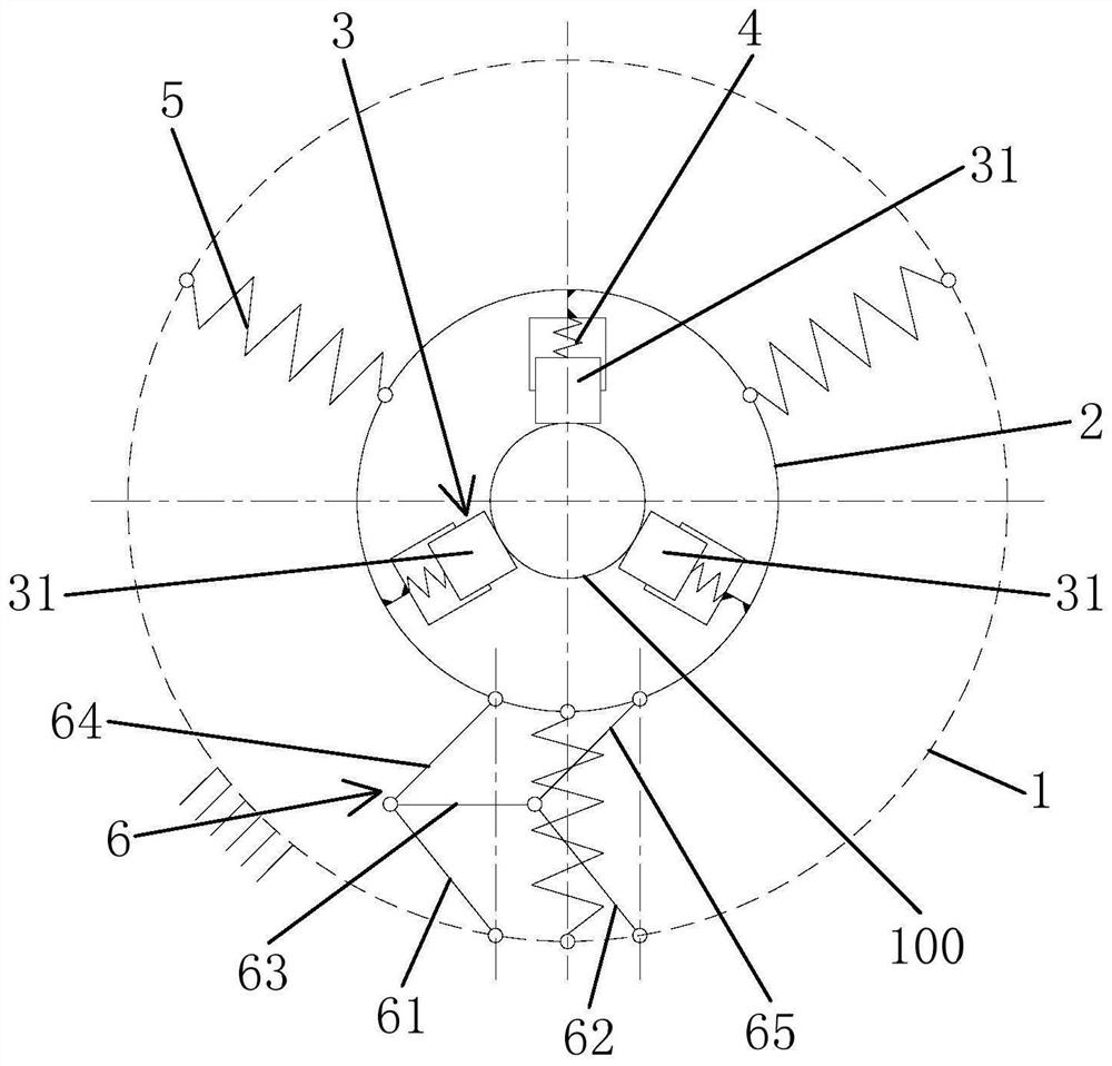
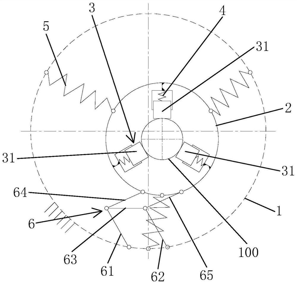
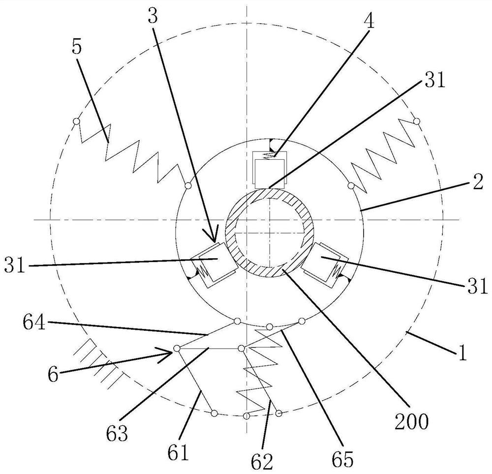
[0034] In order to have a clearer understanding of the technical features, purposes and effects of the present invention, the specific implementation manners of the present invention will now be described with reference to the accompanying drawings. Wherein, the use of adjective or adverbial modifiers "upper" and "lower", "top" and "bottom", "inner" and "outer" is only for relative reference between groups of terms and is not descriptive. Any specific directional constraints on the modified term. In addition, the terms "first", "second" and so on are only used for descriptive purposes, and cannot be understood as indicating or implying relative importance or implicitly specifying the number of indicated technical features. Therefore, the definition of "first" , "second", etc. may expressly or implicitly include one or more of these features. In the description of the present invention, unless otherwise specified, "plurality" means two or more.

[0035] Such as figure 1 , ...


PUM


Abstract

The invention provides a tubing coupling detection device and a reducing pipe column detection device. The tubing coupling detection device comprises a static platform, a movable platform and a detector, wherein the static platform can be fixed to a wellhead and is provided with a first through hole for a pipe column moving axially to penetrate through; the movable platform is movably arranged on the static platform, is provided with a second through hole for the pipe column to penetrate through and can move relative to the static platform along a first plane parallel to the radial plane of the pipe column; and the detector is movably mounted on the movable platform and makes contact with the outer wall of the pipe column, the detector and the movable platform can move along the first plane along with the pipe column and keep relatively static when the pipe column deviates radially, and a tubing coupling of the pipe column enables the detector to move relative to the movable platform and trigger the detector when passing through the detector. The tubing coupling detection device is high in detection accuracy and can meet the requirement for automation of operation under pressure and workover treatment.

Description

technical field [0001] The invention relates to the technical field of oil field hot-press operation, in particular to a detection device for an oil pipe coupling and a detection device for a variable-diameter pipe string. Background technique [0002] With the continuous promotion of snubbing technology, low-pressure snubbing technology has gradually matured, and has changed from special operations to routine operations, in which lifting and lowering pipe strings is the most important operation process, which is highly repetitive and takes up man-hours. , The underpressure operation is always a construction operation under high pressure conditions, and the spirit of the operator is always in a state of high tension. Therefore, in order to reduce the labor intensity of the operator, the demand for automatic underpressure operation has been put forward. The same situation also exists in conventional workover operations, and with the aging of operators, the lack of timely repl...

Claims


Application Information

Patent Timeline
Patent Type & Authority Applications(China)
IPC IPC(8): E21B47/09
CPCE21B47/09Y02E10/10
Inventor 明尔扬
Owner PETROCHINA CO LTD
Learn More