
Calibration method for rotating shaft of numerical control machine tool, device, equipment and storage medium

A calibration method and technology of CNC machine tools, which are applied to automatic control devices, feeding devices, metal processing equipment, etc. Accuracy and easy calibration

Active Publication Date: 2021-12-03
HANS LASER TECH IND GRP CO LTD +1
View PDF10 Cites 1 Cited by
  • Summary
  • Abstract
  • Description
  • Claims
  • Application Information

AI Technical Summary

Problems solved by technology

[0005] The purpose of the embodiment of the present invention is to propose a calibration method, device, equipment and storage medium for the rotary axis of a CNC machine tool, which is used to solve the problem of observing the tip of the tool with the naked eye. Estimating the required compensation amount relative to the alignment point not only greatly increases the energy and time spent by the staff, but also cannot ensure the technical problem of obtaining accurate compensation amount

Method used


Image

  • Calibration method for rotating shaft of numerical control machine tool, device, equipment and storage medium
  • Calibration method for rotating shaft of numerical control machine tool, device, equipment and storage medium
  • Calibration method for rotating shaft of numerical control machine tool, device, equipment and storage medium

Examples


Embodiment Construction

[0074] Unless otherwise defined, all technical and scientific terms used herein have the same meaning as commonly understood by those skilled in the technical field of the embodiments of the present invention; the terms used in the description of the embodiments of the invention herein are only for describing specific The purpose of the embodiment is not intended to limit the embodiment of the present invention; the terms "comprising" and "having" and any variations thereof in the description and claims of the embodiment of the present invention and the description of the above drawings are intended to cover exclusive inclusion. The terms "first" and "second" in the description and claims of the embodiments of the present invention or the above drawings are used to distinguish different objects, rather than to describe a specific order.

[0075] Reference herein to an "embodiment" means that a particular feature, structure, or characteristic described in connection with the em...


PUM


Abstract

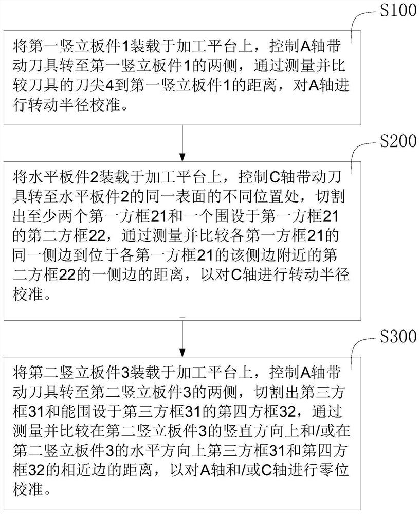
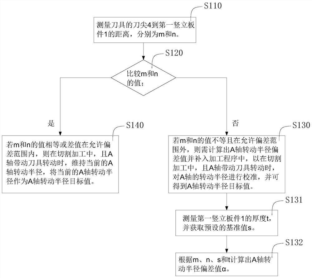
The embodiment of the invention belongs to the technical field of numerical control machining centers, and relates to a calibration method for a rotating shaft of a numerical control machine tool. The method comprises the following steps that rotating radius calibration is carried out on an A shaft by measuring and comparing the distance from a tool nose of a tool to a first vertical plate; rotation radius calibration is carried out on C shaft by measuring and comparing the distance from the same side edge of each first square frame to a position located on one side edge of each second square frame cut on a horizontal plate; and zero position calibration is carried out on the A shaft and / or the C shaft by measuring and comparing the distance between the close edges of a third square frame and a fourth square frame cut on a second vertical plate. The embodiment of the invention further provides a numerical control machining device, equipment and a storage medium. According to the embodiment of the invention, the positions between the A shaft and the C shaft and the plates are changed by rotating the A shaft and the C shaft, the distances between the plates at different positions are measured, or the distances between the plates at different positions after cutting are measured, rotation radius calibration and zero position calibration are carried out on the A shaft and the C shaft, the calibration operation in the whole process is simple, the method is efficient and novel, and the precision is relatively high.

Description

technical field [0001] The embodiments of the present invention relate to the technical field of numerical control machining centers, and in particular to a method, device, equipment and storage medium for calibrating a rotating shaft of a numerical control machine tool. Background technique [0002] A five-axis CNC machining center has five linkage axes, which are three linear axes X, Y, and Z and two rotary axes C and A. Among them, the C axis rotates around the Z axis, and the A axis rotates around the X axis. In the process of using the five-axis CNC machining center, because the C-axis and the A-axis may cause additional movement of the tool tip point during the rotary motion, the control point of the CNC system cannot coincide with the tool tip point. At this time, the control system It is necessary to compensate the C-axis and A-axis separately to ensure that the tool nose point moves according to the specified trajectory of the command. [0003] In order to ensure t...

Claims


Application Information

Patent Timeline
Patent Type & Authority Applications(China)
IPC IPC(8): B23Q15/22B23Q17/22
CPCB23Q15/22B23Q17/2233
Inventor 胡阳欧阳征定何菊翠黄永煜姚玉菲陈茂清刘旭飞周桂兵陈根余陈焱高云峰
Owner HANS LASER TECH IND GRP CO LTD
Learn More