A gun level parallel correction device

A technology of parallel correction and firearms, which is applied in the direction of offensive equipment, aiming devices, and weapon accessories. It can solve the problems of high cost of lasers, the impact of focus and clarity on calibration accuracy, and the impact on calibration accuracy, so as to improve operational efficiency and safety. , Easy batch calibration operation, gun calibration operation simple effect

Inactive Publication Date: 2017-08-29
郭南南
View PDF7 Cites 0 Cited by
  • Summary
  • Abstract
  • Description
  • Claims
  • Application Information

AI Technical Summary

Problems solved by technology

Problems with the laser aiming point correction method: First, the venue is limited, and it cannot be used in places where the light is too strong; second, the distance is limited, and it is difficult for ordinary laser beams to reach 100 meters. When it is beyond 100 meters, the focus and clarity will be affected. Calibration accuracy, the cost of special lasers is too high, it is difficult to popularize the grass-roots use of the army; third, the operation method of the calibration remains unchanged, and human eyes still need to be aimed, and human factors affect the calibration accuracy

Method used


Image

  • A gun level parallel correction device
  • A gun level parallel correction device
  • A gun level parallel correction device

Examples


Embodiment Construction

[0027] The following will clearly and completely describe the technical solutions in the embodiments of the present invention with reference to the accompanying drawings in the embodiments of the present invention. Obviously, the described embodiments are only some, not all, embodiments of the present invention. Based on the embodiments of the present invention, all other embodiments obtained by persons of ordinary skill in the art without creative efforts fall within the protection scope of the present invention.

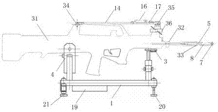
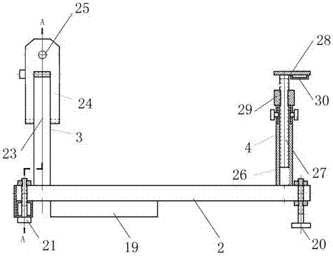
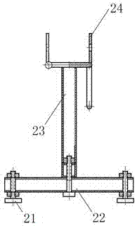
[0028] A gun level parallel correction device, such as Figures 1 to 5 shown, including:

[0029] The gun level adjustment support 1 for placing the gun includes the support chassis 2, and the front support 3 and the rear support 4 at the two ends of the support chassis 2; the gun level adjustment support uses the thread rise angle to realize the height adjustment and Self-locking; the jaw fixing seat and three-point support leg structure are adopted to realize th...


PUM


Abstract

The invention provides gun level collimation equipment. The gun level collimation equipment comprises a gun horizontal adjustment support used for containing a gun, a gun inner bore bubble shaft used for adjusting a gun bore axis and a gun sight line bubble shaft used for adjusting a gun front sight. The gun inner bore bubble shaft comprises an inner bore cross groove elastic locating shaft, an inner bore shaft longitudinal bubble and an inner bore shaft transverse bubble, wherein the inner bore shaft longitudinal bubble and the inner bore shaft transverse bubble are located on the inner bore cross groove elastic locating shaft. The gun sight line bubble shaft comprises a sight line shaft, a sight line shaft longitudinal level bubble, a sight line shaft transverse level bubble and a front sight high-low support, wherein the sight line shaft longitudinal level bubble, the sight line shaft transverse level bubble and the front sight high-low support are arranged on the sight line shaft. By means of the equipment, gun correction operation is quite easy, batched correction operation is easy to implement and repeat, only the corresponding level bubbles need to be centered, aiming and ball firing do not need to be implemented, and errors caused by the individual difference of human eye aiming are avoided; the site is simplified, live shells are saved, and recovering and copying of the gun shooting accuracy can be carried out in batch; and the operation efficiency and safety of gun spotting are improved.

Description

technical field [0001] The invention relates to the technical field of gun calibration equipment, in particular to a gun level parallel calibration equipment. Background technique [0002] There are two main methods of gun calibration at present: live ammunition shooting calibration and instrument calibration, the latter is also called cold calibration. The correction method of live ammunition shooting is to change the impact point by adjusting the front sight in the process of shooting live ammunition, so that the impact point coincides with the expected hit point. Theoretically, the correction can be completed after only one shooting and adjustment. However, the actual shooting correction is restricted by factors such as climate (wind direction), visibility (sunny and cloudy), shooting range conditions, and the shooter's personal experience level. Multiple shootings are often required. calibration to complete. Time-consuming, labor-intensive, bomb-intensive, imprecise, a...

Claims


Application Information

Patent Timeline
Patent Type & Authority Patents(China)
IPC IPC(8): F41G1/54
CPCF41G1/545
Inventor 艾春玲翟顺利
Owner 郭南南
Why Eureka
Try Eureka