Eureka AIR delivers breakthrough ideas for toughest innovation challenges, trusted by R&D personnel around the world.

Ventilation and dust removal device and dust removal method and purification and dehumidification method thereof

A dedusting device and wet dedusting technology, which are applied in combination devices, separation methods, chemical instruments and methods, etc., can solve the problems of clogging filter elements, excessive secondary waste, and high air humidity.

Pending Publication Date: 2021-12-03
CHINA NUCLEAR POWER ENG CO LTD
View PDF9 Cites 1 Cited by
  • Summary
  • Abstract
  • Description
  • Claims
  • Application Information

AI Technical Summary

Problems solved by technology

[0004] The air quality after filtering by the filter element dust filter is good, but due to the high humidity in the mixer, there are problems of hardening and blockage of the filter element after the combination of dust and water vapor, resulting in frequent replacement problems; the dust removal efficiency of wet dust removal filters is generally greater than 90% , up to 99.5%, but it has problems such as large energy consumption, a lot of secondary waste such as waste liquid and mud, and high air humidity after filtration.

Method used


Image

  • Ventilation and dust removal device and dust removal method and purification and dehumidification method thereof
  • Ventilation and dust removal device and dust removal method and purification and dehumidification method thereof
  • Ventilation and dust removal device and dust removal method and purification and dehumidification method thereof

Examples


Embodiment Construction

[0070] The present invention will be further described below in conjunction with the accompanying drawings and specific embodiments.

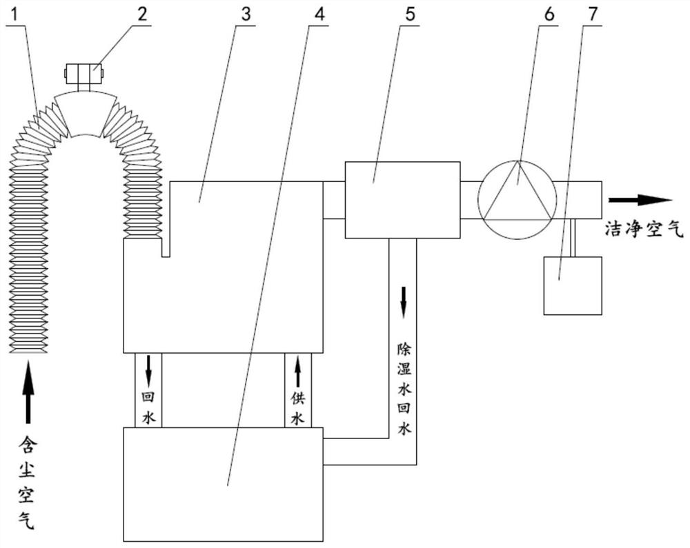
[0071] like figure 1 As shown, a kind of ventilation and dust removal device provided by the present invention is arranged on the air outlet of the mixer of the cement curing line in the cement curing plant of the nuclear power plant, including dust collection hose 1, dust falling vibrator 2, wet dust removal filter 3. The first water tank 4, the condensation dehumidification device 5, the exhaust fan 6, and the air monitoring device 7. The dusty air discharged from the mixer of the cement curing line enters the wet dust filter 3 through the dust collection hose 1 for dust removal, then enters the condensation dehumidification device 5 for dehumidification, and is treated as clean air. Discharging; the dust removal operation in the wet dust removal filter 3 is realized by using the circulating water in the first water tank 4 .

[0072] Among ...


PUM


Abstract

The invention belongs to the technical field of nuclear facility ventilation, and particularly relates to a ventilation and dust removal device, a dust removal method of the ventilation and dust removal device and a purification and dehumidification method of the ventilation and dust removal device. The ventilation and dust removal device is arranged on an air outlet of a mixer of a cement solidification line of a nuclear power station. The ventilation and dust removal device comprises a wet dust removal filter (3), the air inlet end of the wet dust removal filter (3) communicates with a dust collection hose (1), the air outlet end of the wet dust removal filter (3) communicates with a condensation dehumidification device (5). The ventilation and dust removal device further comprises a first water tank (4) connected with the wet dust removal filter (3). The air inlet end of the dust collection hose (1) is connected with an air outlet of the mixer. Dust-containing air discharged from the mixer enters the wet dust removal filter (3) through the dust collection hose (1) for dust removal, then enters the condensation dehumidification device (5) for dehumidification treatment to form clean air to be discharged; and the dust removal is realized by circulating water in the first water tank (4). On the premise of meeting the air exhaust quality requirement, a large amount of dry cement materials are prevented from being lost due to ventilation, meanwhile, the water consumption is reduced, and the output of secondary waste is reduced.

Description

technical field [0001] The invention belongs to the technical field of nuclear facility ventilation, and in particular relates to a ventilation and dust removal device, a dust removal method, and a purification and dehumidification method. Background technique [0002] The cement solidification line belongs to the solid waste treatment system of the nuclear power plant. Its function is to mix radioactive waste with cement dry material, put them into standard steel drums and seal them to form a hard solidified body for storage. In the mixer of cement dry material and radioactive waste, due to the input of cement dry material, a large amount of cement dust will fly; and the conveying pipeline of cement dry material needs to be continuously fed with dry hot air to avoid cement hardening and blockage caused by moisture in the mixer , further exacerbated the floating of cement dust. Therefore, the mixer needs to be equipped with an efficient ventilation and dust removal system, ...

Claims


Application Information

Patent Timeline
IPC IPC(8): B01D50/00B01D45/08B01D47/06B01D53/26
CPCB01D50/00B01D45/08B01D47/06B01D53/261B01D2257/80
Inventor 郭建伟石兵刘国彪张耀春
Owner CHINA NUCLEAR POWER ENG CO LTD
Why Eureka
Eureka Blog
Learn More