Mining rock drift heading machine

A roadheader and rock roadway technology, which is applied in the field of mine rock roadway roadheaders, can solve the problems that the bolter drilling machine is not perpendicular to the tunnel wall, the working mode affects the equipment's tunneling efficiency, and the bolt cannot play a safe anchoring role. , to achieve the effect of saving the time and work of artificial slag removal, improving space utilization and compact equipment

Pending Publication Date: 2021-11-30
江苏神盾工程机械有限公司
View PDF0 Cites 0 Cited by
  • Summary
  • Abstract
  • Description
  • Claims
  • Application Information

AI Technical Summary

Problems solved by technology

[0003] In the structure of the traditional TBM roadheader, the rock bolts are arranged symmetrically on both sides of the main beam. When the equipment is stationary, the bolts on both sides perform anchoring work. The wall of the tunnel cannot be vertical, and the installed bolts cannot achieve the safe anchoring effect required by the mine, which does not meet the support requirements of the coal mine, and the working mode of the bolter affects the driving efficiency of the equipment
[0004] The main beam of the traditional TBM roadheader is affected by the support shoes, and the center is dislocated upward. The belt conveyor of the main engine is installed in the inner cavity of the main beam, and it also transports the slag in an upward posture. Head overlap, this layout method increases the length of the belt conveyor, and because the belt conveyor is arranged inside the main beam and extends through the steel beam to the rear support, when the gangue falls during the excavation process of the roadheader, the There is no equipment at the location of the main engine to transport the gangue away, resulting in the accumulation of gangue and difficulty in excavation

Method used


Image

  • Mining rock drift heading machine

Examples


Embodiment 1

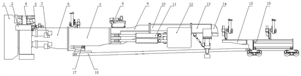
[0022] see figure 1 , the present invention provides a technical solution: a mining rock roadway boring machine, including a tunneling system, a tensioning propulsion system, a support system, a conveying system, a dust removal system, and a supporting system 16; The shield 2 and the main drive 3 are composed of shields 2 on the top, bottom, left, and right sides of the main drive 3, and the cutter head 1 is installed at the end of the main drive 3;

[0023] The tension propulsion system includes the front main beam 6, the drilling rig beam 7, the transition beam 9, the sliding beam 10, the rear support 13, the propulsion system 11 and the tension system 12, the active drive 3 is installed on the front main beam 6, and the front main beam 6 Connected with the drilling rig beam 7, the propulsion system 11 is installed on both sides of the transition beam 9 and the sliding beam 10, the tensioning system 12 is installed on the sliding beam 10, and one end of the propulsion system...


PUM


Abstract

The invention discloses a mining rock drift heading machine. The mining rock drift heading machine comprises a heading system, a tight supporting and propelling system, a supporting system, a conveying system, a dust removal system and a rear matching system; the tunneling system is composed of a cutterhead, a shield and a main drive, a belt conveyor layout and a transferring slag conveying mode are adopted, the tunneling system is suitable for mine roadway tunneling, and falling gangues are very convenient to clean and convey; the adopted vertical anchor rod drilling machine and the like are arranged on the central axis of a main beam and a trailer and driven by a rotating device, the punching angle is perpendicular to the tunnel wall, the mine supporting requirement is met, the adopted vertical anchor rod drilling machine can synchronously conduct anchor rod punching and anchor rod supporting in the equipment tunneling process, tunneling and supporting are synchronous, and the construction efficiency is improved; and according to a dust removal fan, a steel structure cavity of the main beam and a rear support serves as an air duct channel, the space utilization rate is increased, equipment is compact, meanwhile, waste generated in the dust removal process can directly fall onto a belt conveyor, time and work for manual slag removal are saved, and work efficiency is improved.

Description

technical field [0001] The invention belongs to the technical field of rock roadway tunnel excavation equipment, and in particular relates to a mining rock roadway boring machine. Background technique [0002] TBM roadheader is a machine that uses mechanical energy to crush rocks and continuously outputs the fallen rocks backwards. It has been widely used in transportation, water conservancy and other fields. In recent years, its application in the field of coal mines has achieved certain results. Compared with the blasting method of traditional coal mining, TBM roadheader has faster tunneling speed, higher support efficiency, better construction safety, and can be applied to different geological conditions. Therefore, TBM roadheader is being used more and more Many coal mining enterprises attach importance to it. [0003] In the structure of the traditional TBM roadheader, the rock bolts are arranged symmetrically on both sides of the main beam. When the equipment is stat...

Claims


Application Information

Patent Timeline
Patent Type & Authority Applications(China)
IPC IPC(8): E21D9/08E21D20/00E21D19/00E21D9/12E21F5/20E21F1/04
Inventor 秦立学马士涛张鸿麟许长飞许婉莹马士建朱永明王福松黄李文辛龙高亮周超
Owner 江苏神盾工程机械有限公司
Why Eureka
Try Eureka