Mini quantum dot LED and manufacturing method thereof

A technology of quantum dots and quantum dot layers, applied in electrical components, circuits, semiconductor devices, etc., can solve the problems of reducing blue light excitation effect and blue light utilization rate, complex manufacturing process of quantum dot fluorescent film, and high manufacturing cost of quantum dot fluorescent film , to achieve the effect of reducing processing and adding processes, reducing thickness and prolonging life.

Pending Publication Date: 2021-11-26
ANHUI COREACH TECH
View PDF0 Cites 0 Cited by
  • Summary
  • Abstract
  • Description
  • Claims
  • Application Information

AI Technical Summary

Problems solved by technology

[0005] 1) The existing LED plus quantum dot fluorescent film is produced by different manufacturers and assembled in the display terminal factory. There is a certain gap between the LED and the quantum dot fluorescent film, and the gap is generally 10-40mm; It is difficult to guarantee the consistency of the product when one manufacturer completes the quantum dot fluorescent film and another manufacturer completes it;
[0006] 2) The blue light emitted by the LED excites the quantum dots in the quantum dot fluorescent film to produce white light. Due to the large distance between the quantum film and the LED, there is no adhesive medium in the middle except air, which reduces the excitation effect of blue light and the utilization of blue light. Rate;
[0007] 3) The manufacturing cost of the quantum dot fluorescent film is high, and the dosage is large, which is the same size as the display terminal;
[0008] 4) The manufacturing process of quantum dot fluorescent film is complex;
[0009] 5) The distance between the quantum film and the LED is large, and the dynamic contrast effect is poor

Method used


Image

  • Mini quantum dot LED and manufacturing method thereof
  • Mini quantum dot LED and manufacturing method thereof
  • Mini quantum dot LED and manufacturing method thereof

Examples


Embodiment Construction

[0050] The purpose of the present invention can be achieved through the following technical solutions:

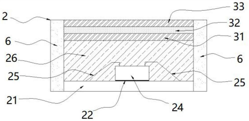
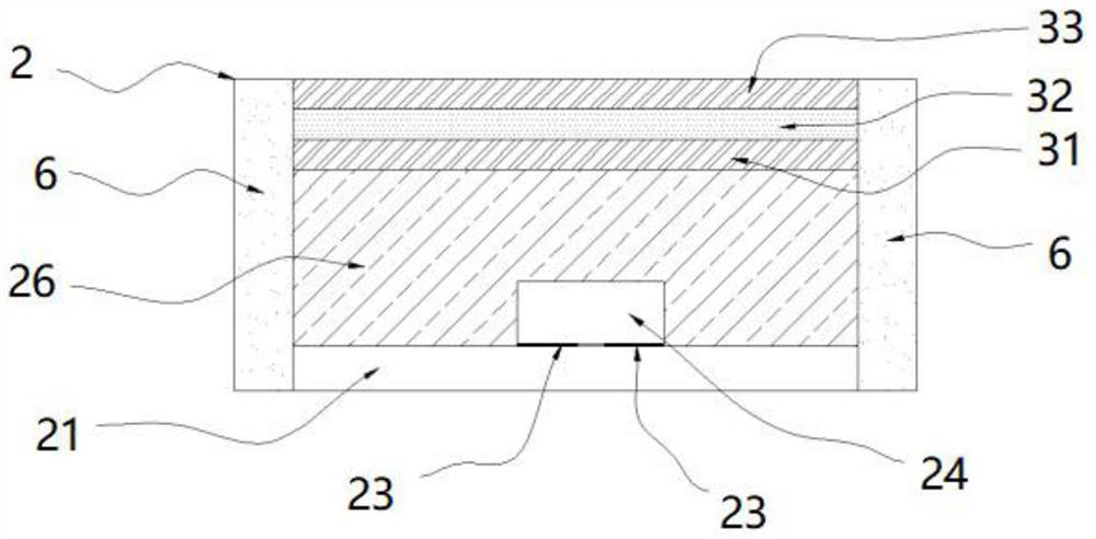
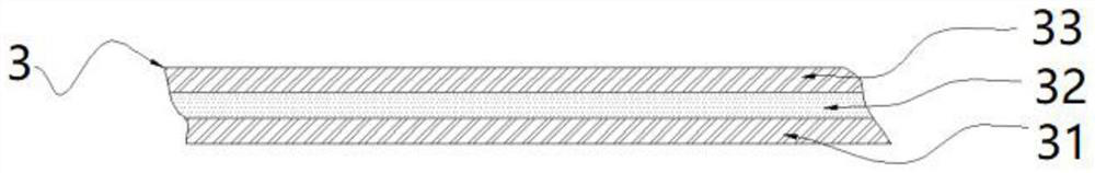
[0051] A Mini quantum dot LED, see Figure 1~3 , including LED lamp beads 2, quantum dot fluorescent film 3, and side walls;

[0052] The inner top layer of the LED lamp bead 2 is provided with a quantum dot fluorescent film 3, and the quantum dot fluorescent film 3 contains a quantum dot layer 32; the LED lamp bead 2 and the quantum dot fluorescent film 3 are integrated to directly emit white light, and the No gap, reducing the thickness of the combination of LED lamp beads and quantum dot fluorescent film, which is conducive to the development of ultra-thin backlight modules; using LED lamp bead-level quantum dot fluorescent film3, compared with the traditional full-layer quantum dot fluorescent film solution , greatly reducing the amount of quantum dot fluorescent film used; the top layer of the LED lamp bead 2 is directly covered with quantum dot fluorescent film 3, re...


PUM

PropertyMeasurementUnit
Thicknessaaaaaaaaaa
Thicknessaaaaaaaaaa

Abstract

The invention discloses a Mini quantum dot LED and a manufacturing method thereof. The Mini quantum dot LED comprises an LED lamp bead and a quantum dot fluorescent film. The quantum dot fluorescent film is arranged on the top layer in the LED lamp bead, and a quantum dot layer is arranged in the quantum dot fluorescent film; the quantum dot fluorescent film comprises a bottom layer water-oxygen barrier layer, a quantum dot layer and a top layer water-oxygen barrier layer, the quantum dot layer is located between the bottom layer water-oxygen barrier layer and the top layer water-oxygen barrier layer, and the bottom layer water-oxygen barrier layer is arranged on the bottom side of the quantum dot layer; a top water-oxygen barrier layer is arranged on the top side of the quantum dot layer; and the bottom layer water-oxygen barrier layer covers the transparent adhesive layer in the LED lamp beads. The Mini quantum dot LED has the characteristics of eliminating the gap between the quantum dot and the LED lamp bead, reducing the thickness of the module, reducing the use amount of the quantum dot fluorescent film, reducing the manufacturing cost and prolonging the service life.

Description

technical field [0001] The invention relates to a Mini quantum dot LED and a manufacturing method thereof, in particular to a Mini quantum dot LED with the functions of eliminating the gap between the quantum dot and the LED lamp bead, reducing the thickness of the module, reducing the amount of fluorescent film of the quantum dot, reducing the manufacturing cost, and prolonging the service life. Mini quantum dot LED and manufacturing method thereof. Background technique [0002] The appearance of LCD liquid crystal display technology has been more than 30 years. Since the LCD itself does not emit light, it must rely on a light source. Usually, the molecular arrangement of the liquid crystal molecules is disordered when the power is not applied. The disordered state becomes that the molecules are arranged in an orderly manner when the electricity is turned on, and deflection occurs, so that the light passes through, forming uneven light and shade, and then forming an image. ...

Claims


Application Information

Patent Timeline
IPC IPC(8): H01L33/50H01L33/54
Inventor 丁磊李泉涌王鹏生彭友
Owner ANHUI COREACH TECH
Why Eureka
Try Eureka