
Medical imaging equipment

A technology of medical imaging and equipment, applied in the field of medical imaging, can solve problems affecting imaging quality, vibration, and damage to shim strip structure, and achieve the effects of improving imaging quality, simple and convenient operation, and easy insertion and removal

Pending Publication Date: 2021-11-26
UNITED IMAGING RES INST OF INNOVATIVE MEDICAL EQUIP
View PDF0 Cites 1 Cited by
  • Summary
  • Abstract
  • Description
  • Claims
  • Application Information

AI Technical Summary

Problems solved by technology

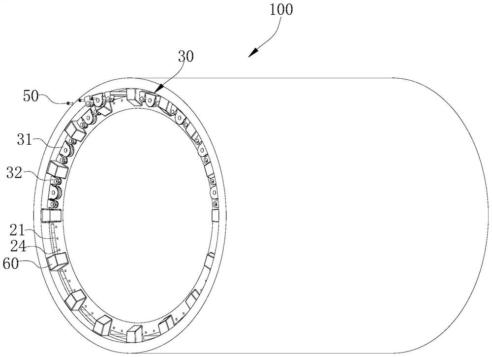
[0003] Medical imaging equipment includes a main magnet, gradient coils and shim components. The main magnet is used to generate a uniform magnetic field; the gradient coil is located in the aperture of the main magnet to generate a gradient magnetic field that is linearly distributed in space; In the shimming hole of the coil; when scanning, the gradient coil passes a changing current, and under the action of the changing Lorentz force, it will produce severe vibration; the vibration of the gradient coil will cause the shimming hole installed in the shimming hole The field component vibrates at high frequency and low displacement, which will affect the imaging quality, and in severe cases, the structure of the shim strip will be damaged
[0004] Currently, at least one end of the shimming component is connected to the gradient coil through a screw, but the shimming component will still vibrate at high frequency and low displacement in the shimming hole, thus affecting the imaging quality

Method used


Image

  • Medical imaging equipment
  • Medical imaging equipment
  • Medical imaging equipment

Examples


Embodiment Construction

[0046]The technical solutions in the embodiments of the present invention will be clearly and completely described below in conjunction with the accompanying drawings in the embodiments of the present invention. Obviously, the described embodiments are only part of the embodiments of the present invention, not all of them. Based on the implementation manners in the present invention, all other implementation manners obtained by persons of ordinary skill in the art without making creative efforts belong to the scope of protection of the present invention.

[0047] It should be noted that when a component is said to be "mounted on" another component, it may be directly mounted on another component or there may be an intervening component. When a component is said to be "set on" another component, it may be set directly on the other component or there may be an intervening component at the same time. When a component is said to be "fixed" to another component, it may be directly ...


PUM


Abstract

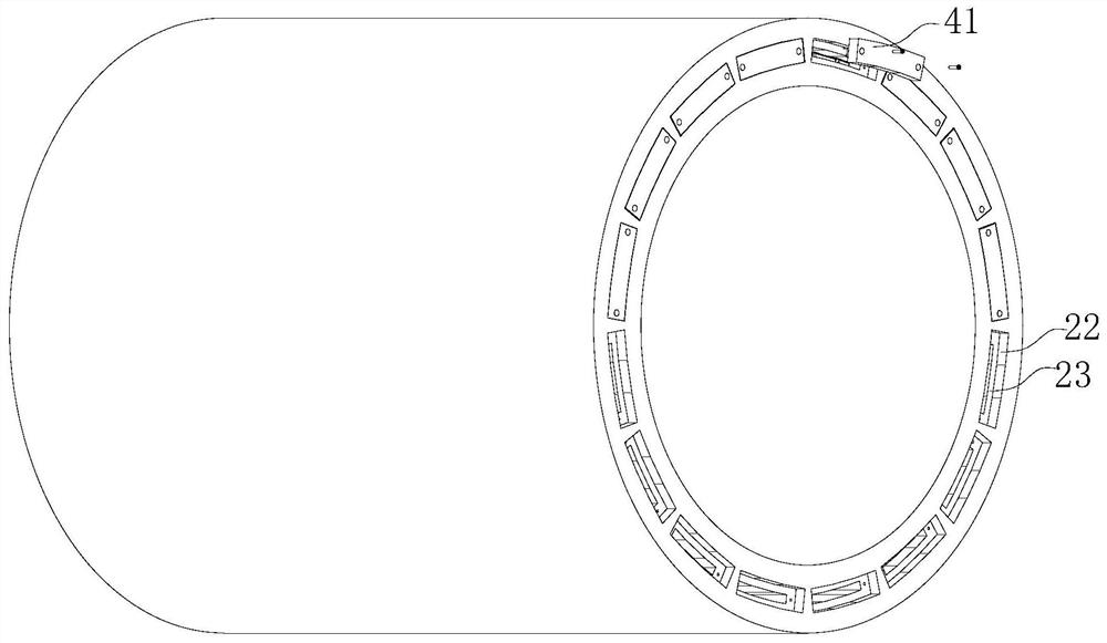
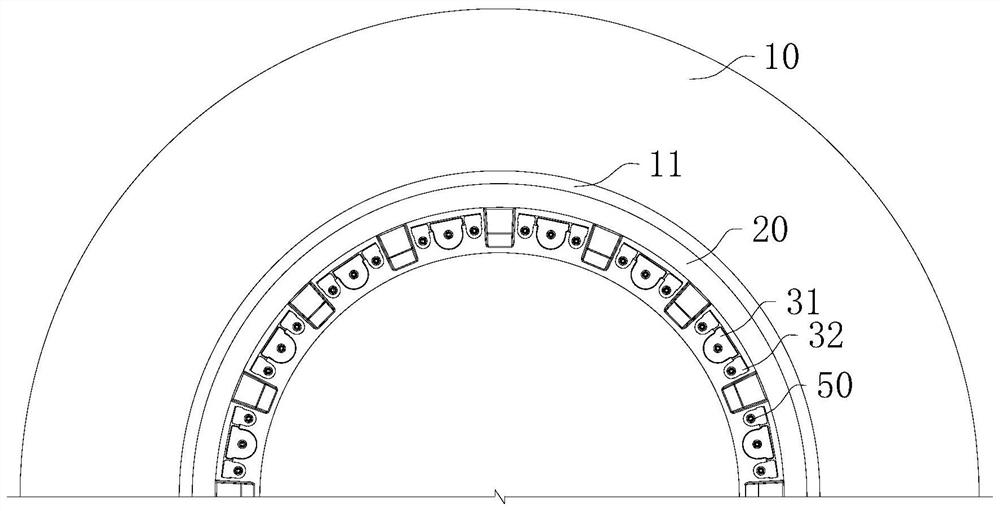
The invention relates to the technical field of medical imaging, in particular to medical imaging equipment. The medical imaging equipment comprises a main magnet, a gradient coil, a shimming assembly and an elastic piece, the main magnet is provided with an installation hole penetrating through the two ends of the main magnet, the gradient coil is installed in the installation hole, the gradient coil is provided with a shimming hole extending in the axis direction of the gradient coil, and the shimming assembly is installed in the shimming hole; the elastic piece is located at the end of the shimming assembly, and at least one end of the shimming assembly is pressed in the shimming hole through the elastic piece. The equipment has the advantages that on one hand, the resilience force of the elastic piece can enable the shimming assembly to be tightly attached to the inner wall of the shimming hole, so that the installation gap between the shimming assembly and the shimming hole is reduced, excitation vibration of the shimming assembly in the shimming hole is avoided, and the imaging quality is improved; on the other hand, due to the arrangement of the elastic piece, operation is easy and convenient, the shimming assembly can be conveniently inserted and taken out, and the shimming assembly can be stably fixed.

Description

technical field [0001] The invention relates to the technical field of medical imaging, in particular to a medical imaging device. Background technique [0002] Magnetic resonance imaging is a medical imaging technique that uses magnetic resonance phenomena for imaging. The basic principle is that when the measured object is placed in a special magnetic field, the hydrogen atoms in the body can be polarized, and the hydrogen nuclei in the human body are excited by radio frequency pulses, causing the hydrogen nuclei to resonate and absorb energy. After the radio frequency pulse is stopped, Hydrogen nuclei emit radio signals at a specific frequency, and release the absorbed energy, which is received by a receiver outside the body and converted and processed by a computer to obtain an image. [0003] Medical imaging equipment includes a main magnet, gradient coils and shim components. The main magnet is used to generate a uniform magnetic field; the gradient coil is located in...

Claims


Application Information

Patent Timeline
Patent Type & Authority Applications(China)
IPC IPC(8): G01R33/48G01R33/38A61B5/055
CPCG01R33/48G01R33/38A61B5/055
Inventor 张楠
Owner UNITED IMAGING RES INST OF INNOVATIVE MEDICAL EQUIP
Learn More