Intelligent door lock speed reducer with centrifugal clutch

A technology for centrifugal clutches and smart door locks, applied in clutches, automatic clutches, non-mechanical transmission-operated locks, etc., can solve the problems of complex structure, high cost, and large volume of the reducer, and achieve simple structure, reduced space size, cost reduction effect

Pending Publication Date: 2021-11-26
深圳市盛俊智能家居科技有限公司
View PDF0 Cites 0 Cited by
  • Summary
  • Abstract
  • Description
  • Claims
  • Application Information

AI Technical Summary

Problems solved by technology

[0006] The technical problem to be solved by the present invention is that the existing intelligent door lock reducer has complex structure, large volume and high cost

Method used


Image

  • Intelligent door lock speed reducer with centrifugal clutch
  • Intelligent door lock speed reducer with centrifugal clutch
  • Intelligent door lock speed reducer with centrifugal clutch

Examples


Embodiment 1

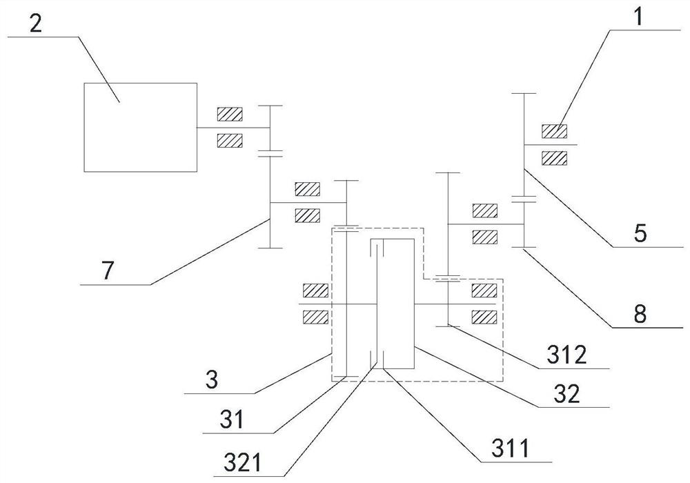
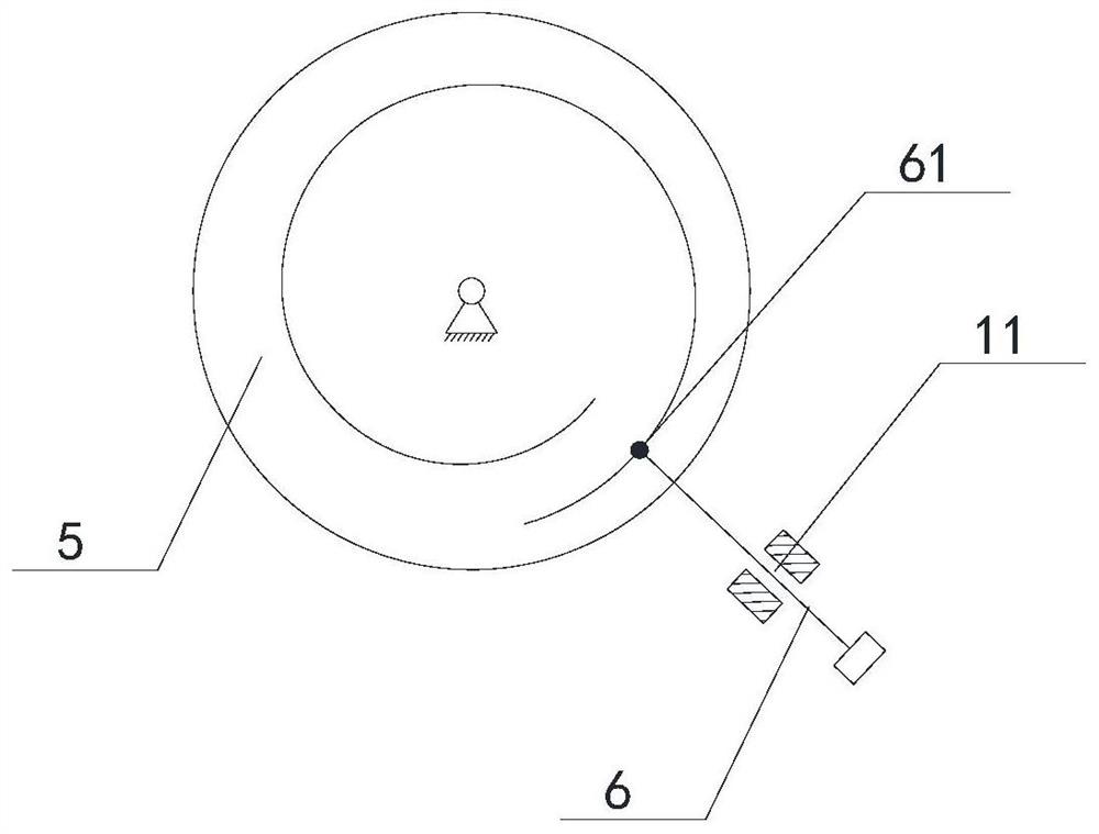
[0051] The intelligent door lock reducer with centrifugal clutch provided by the present invention includes a reducer housing 1, a drive motor 2, a centrifugal clutch 3 and a state mechanism, the state mechanism includes an output gear 5 and a slider 6, and the drive motor 2 is arranged on the reducer casing On the body 1, the driving motor 2 and the output gear 5 are connected with the centrifugal clutch 3 respectively.

[0052] The centrifugal clutch 3 includes a centrifugal driven wheel 31 and a centrifugal driving wheel 32 arranged in rotation. The centrifugal driven wheel 31 is provided with a first limiting portion 311 and a driven side gear 312 is provided on its outer surface. A centrifugal elastic component is disposed inside the centrifugal driving wheel 32 , and a second limiting portion 321 is disposed on a side of the centrifugal elastic component. The outer surface of the centrifugal driving wheel 32 is provided with a driving side gear 322, the driving side gear...

Embodiment 2

[0061] Such as Figure 5 and Figure 6 As shown, the driven side gear 31 is a cylinder with the opening downward, the driven side gear 312 is arranged on the top surface of the cylinder, the inner surface of the cylinder is provided with a limiting groove 3110, and the top surface of the cylinder is provided with an upper connection. Column 314.

[0062] The driving side gear 32 includes a bottom plate 325 and a supporting wall 326 , the side of the bottom plate 325 is provided with a driving side gear 322 , and the driving side gear 322 meshes with the first reduction assembly 7 . A lower connecting column 327 is provided on the center of the top surface of the bottom plate 325 , and when the driven side gear 312 and the driving side gear 322 are fastened together, the lower connecting column 327 abuts against the upper connecting column 314 . The support wall 326 is disposed on the top surface of the bottom plate 325 , and the notch 3250 is disposed on the support arm 326 ...


PUM


Abstract

The invention discloses an intelligent door lock speed reducer with a centrifugal clutch. The intelligent door lock speed reducer comprises a speed reducer shell and a driving motor and further comprises the centrifugal clutch and a state mechanism, wherein the centrifugal clutch comprises a centrifugal driven wheel and a centrifugal driving wheel which are rotationally arranged; a first limiting part is arranged in the centrifugal driven wheel; a centrifugal elastic assembly with a second limiting part arranged on the side surface is arranged in the centrifugal driving wheel; the centrifugal driving wheel is in transmission connection with the driving motor; the centrifugal elastic assembly elastically deforms under the action of centrifugal force along with rotation of the centrifugal driving wheel, the second limiting part is matched with the first limiting part, and the centrifugal driving wheel and the centrifugal driven wheel are connected into a whole; and the state mechanism comprises an output gear and a sliding block, the output gear is in transmission connection with a driven side gear, and the sliding block slides on the speed reducer shell along with rotation of the output gear. The speed reducer is simple in structure; transmission connection and separation of the output gear and the motor are achieved through the centrifugal clutch; and no additional motor needs to be arranged, so that the cost and the space occupied by the speed reducer are reduced.

Description

technical field [0001] The invention relates to the technical field of intelligent door locks, in particular to an intelligent door lock reducer with a centrifugal clutch. Background technique [0002] The safety, convenience and anti-theft functions of smart door locks meet the needs of mass users, and are also being recognized by most users, becoming a product of the smart home era. In the future, with the help of the power of smart home, smart door locks will become a trend and enter thousands of households. With the continuous increase of people's safety awareness and the continuous development of security technology, traditional mechanical locks will be replaced by smart door locks. The smart door lock can be adapted to the anti-theft doors and wooden doors in the market. The smart door lock can be universally interchanged without changing the lock cylinder. The lock body can be selected according to the needs of the field. Maybe other functions. [0003] There is a c...

Claims


Application Information

Patent Timeline
IPC IPC(8): F16D43/02E05B47/00
CPCF16D43/02E05B47/0012E05B2047/0027E05B2047/002
Inventor 朱丰
Owner 深圳市盛俊智能家居科技有限公司
Why Eureka
Try Eureka