
Exhaust valve seat and compressor

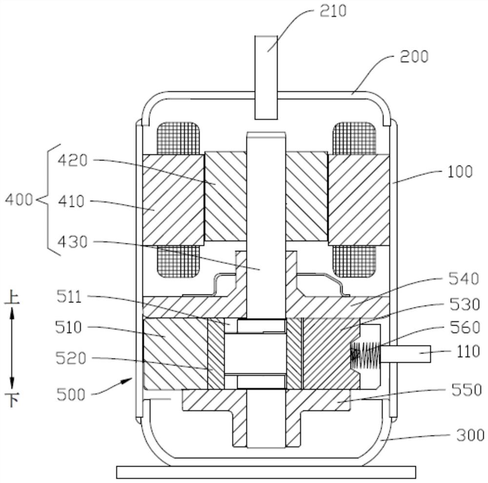
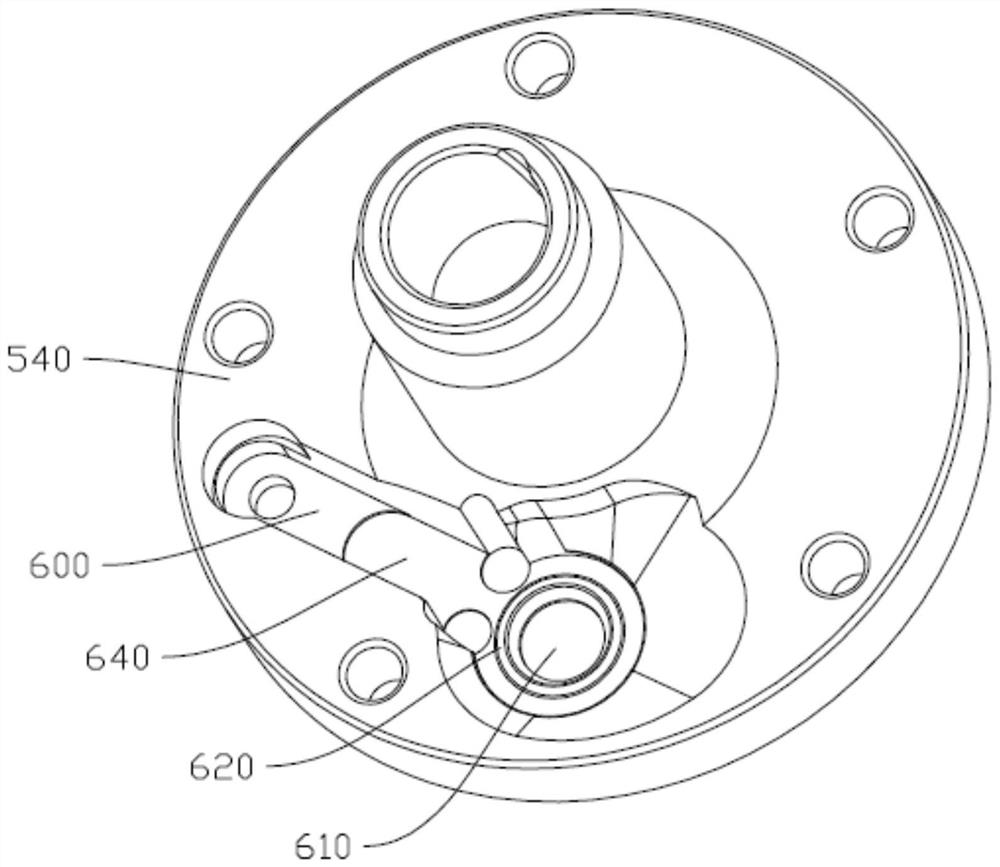
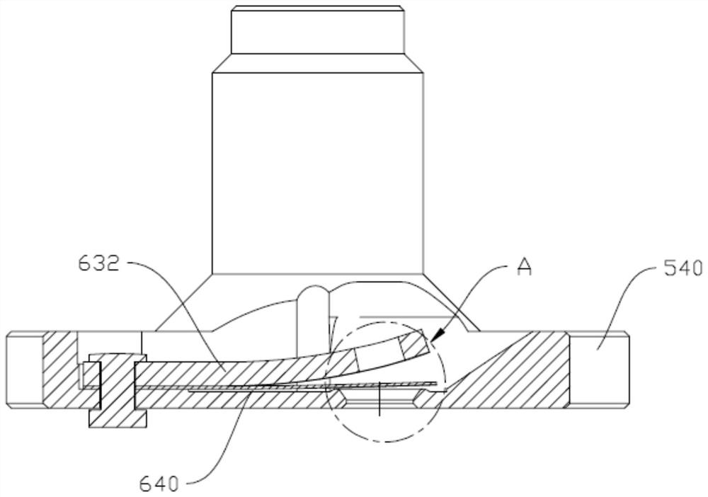
An exhaust valve and valve seat technology, applied in mechanical equipment, machinery/engine, liquid variable capacity machinery, etc., can solve the problem of increasing local exhaust resistance, reducing exhaust flow area, and increasing compressor power consumption and other problems, to achieve the effect of reducing exhaust resistance, reducing eddy current, and reducing power consumption

Active Publication Date: 2021-11-26
GUANGDONG MEIZHI COMPRESSOR
View PDF8 Cites 0 Cited by
  • Summary
  • Abstract
  • Description
  • Claims
  • Application Information

AI Technical Summary

Problems solved by technology

[0002] In the related technology, the exhaust structure of the compressor is mainly a straight-through design. During the exhaust process, when the airflow enters the exhaust hole, the airflow is separated on the surface layer of the exhaust hole, causing vortex phenomenon, and the exhaust local resistance increases. , resulting in a decrease in the effective exhaust flow area and an increase in the power consumption of the compressor; when the airflow leaves the exhaust hole, the airflow velocity is high, the pressure is low, and the exhaust resistance is large, which also increases the power consumption of the compressor and the noise

Method used


Image

  • Exhaust valve seat and compressor
  • Exhaust valve seat and compressor
  • Exhaust valve seat and compressor

Examples


Embodiment Construction

[0035] Embodiments of the present invention are described in detail below, examples of which are shown in the drawings, wherein the same or similar reference numerals designate the same or similar elements or elements having the same or similar functions throughout. The embodiments described below by referring to the figures are exemplary only for explaining the present invention and should not be construed as limiting the present invention.

[0036] In the description of the present invention, it should be understood that the orientation descriptions, such as up, down, front, back, left, right, etc. indicated orientations or positional relationships are based on the orientations or positional relationships shown in the drawings, and are only In order to facilitate the description of the present invention and simplify the description, it does not indicate or imply that the device or element referred to must have a specific orientation, be constructed and operated in a specific ...


PUM


Abstract

The invention discloses an exhaust valve seat and a compressor. The exhaust valve seat comprises a valve seat body, the valve seat body is provided with an exhaust hole, the exhaust hole is sequentially provided with a necking part, a transition part and a flaring part in the exhaust direction, and in the exhaust direction, the cross sectional area of the necking part is decreased progressively, and the cross sectional area of the flaring part is increased progressively. The inner wall of the necking part and the inner wall of the flaring part are respectively connected with the inner wall of the transition part; and the axial height of the necking part is H1, the axial height of the transition part is H2, the axial height of the flaring part is H3, and (H1+H2) / (H1+H2+H3) is larger than or equal to 0.2 and smaller than or equal to 0.8. According to the exhaust valve seat, the gas vortex phenomenon at an inlet and an outlet of an exhaust hole can be reduced, the exhaust resistance is reduced, the power consumption of the compressor is reduced, and the energy efficiency of the compressor is effectively improved.

Description

technical field [0001] The invention relates to the technical field of electrical equipment, in particular to an exhaust valve seat and a compressor. Background technique [0002] In the related technology, the exhaust structure of the compressor is mainly a straight-through design. During the exhaust process, when the airflow enters the exhaust hole, the airflow is separated on the surface layer of the exhaust hole, causing vortex phenomenon, and the exhaust local resistance increases. , resulting in a decrease in the effective exhaust flow area and an increase in the power consumption of the compressor; when the airflow leaves the exhaust hole, the airflow velocity is high, the pressure is low, and the exhaust resistance is large, which also increases the power consumption of the compressor and the noise . Contents of the invention [0003] The present invention aims to solve at least one of the technical problems existing in the prior art. Therefore, the present inven...

Claims


Application Information

Patent Timeline
Patent Type & Authority Applications(China)
IPC IPC(8): F04B37/12F04B39/10F04B39/00
CPCF04B37/12F04B39/10F04B39/00Y02T10/12
Inventor 陈中贵黄健锵李云龙龚福宝
Owner GUANGDONG MEIZHI COMPRESSOR
Learn More