
An underground building anti-floating pressure relief hole plugging structure and its construction method

A technology for underground construction and construction methods, applied in infrastructure engineering, construction, protection devices, etc., can solve the problems of difficult sealing, easy formation of gaps, poor sealing effect, etc., to ensure construction quality and avoid leakage. , the effect of extending the seepage path

Active Publication Date: 2022-02-22
SHANDONG SANJIAN CONSTR ENG
View PDF5 Cites 0 Cited by
  • Summary
  • Abstract
  • Description
  • Claims
  • Application Information

AI Technical Summary

Problems solved by technology

However, after the opening of the hole for pressure relief is completed, how to effectively seal the hole is a problem that plagues the construction personnel.
Generally, plugging mortar is used for direct plugging, but it is difficult to plug with water, and gaps are easy to form between the plugging mortar and the original concrete structure, the plugging effect is poor, and leakage in the later stage is easy to occur

Method used


Image

  • An underground building anti-floating pressure relief hole plugging structure and its construction method
  • An underground building anti-floating pressure relief hole plugging structure and its construction method
  • An underground building anti-floating pressure relief hole plugging structure and its construction method

Examples


Embodiment 1

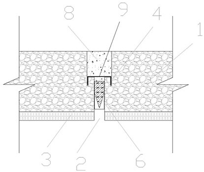
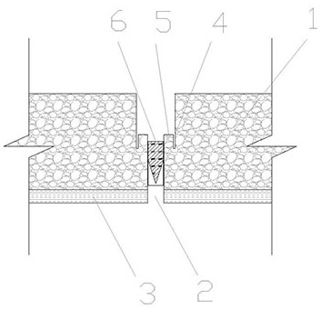
[0033] Figure 1 to Figure 4 Shown is an underground building anti-floating pressure relief hole plugging structure, including a concrete cushion 3, a concrete floor layer 1 and a pressure relief hole 2, the upper part of the pressure relief hole 2 has an annular platform, and it is characterized in that the annular platform There is an annular groove 4 on the top, and a sealing plug 6 is arranged in the pressure relief hole 2. There is a water-stop buckle 9 above the sealing plug 6, and the water-stop buckle 9 fits in the annular groove 4 , the top of the water-stop buckle 9 is a concrete sealing layer 8 .

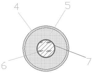
[0034] Such as image 3 As shown, the annular groove 4 and the annular platform are arranged concentrically. The arrangement of the annular groove 4 makes the annular platform form an annular boss 5, and the two are arranged concentrically, so that the thickness of the annular boss 5 is more uniform and the strength is higher.

[0035] The outside of the sealing plug 6...

Embodiment 2

[0041] The construction method of the anti-floating pressure relief hole plugging structure of the above-mentioned underground building comprises the following steps:

[0042] (1) The upper part of the pressure relief hole 2 is provided with an annular platform on the concrete floor layer 1;

[0043] (2) Open an annular groove 4 on the annular platform;

[0044] (3) Put the plug 6 tightly into the pressure relief hole 2;

[0045] (4) Press the water stop buckle 9 into the annular groove 4;

[0046] (5) Pour concrete above the water-stop buckle 9 to seal it.

[0047] In the step (3), the rubber tube 7 is tightly set on the sealing plug 6, and then it is smashed into the pressure relief hole 2 to leave a hole.

[0048] In step (3), the water in the opening of the pressure relief hole 2 and the annular groove 4 is cleaned first, and then the plugging cement slurry is poured above the sealing plug 6 until the annular groove 4 is at least filled.

[0049] The concrete in the co...


PUM


Abstract

The invention belongs to the technical field of building anti-floating construction, and in particular relates to an underground building anti-floating pressure relief hole plugging structure and a construction method thereof. It includes a concrete cushion, a concrete floor and a pressure relief hole. There is an annular platform on the upper part of the pressure relief hole. There is an annular groove on the annular platform. A sealing plug is arranged in the pressure relief hole. There is a water-stop buckle, the water-stop buckle fits in the annular groove, and the top of the water-stop buckle is a concrete sealing layer. The method includes the following steps: setting up an annular platform on the concrete floor at the upper part of the pressure relief hole; opening an annular groove on the annular platform; placing the sealing plug tightly into the pressure relief hole; pressing the water-stop buckle into the annular groove Inside; pour concrete above the waterstop buckle for closure. The structure of the invention is stronger and more stable, and the construction water-stopping effect is better.

Description

technical field [0001] The invention belongs to the technical field of building anti-floating construction, and in particular relates to an underground building anti-floating pressure relief hole plugging structure and a construction method thereof. Background technique [0002] In recent years, with the development of the country and the progress of the industry, the development of construction technology is changing with each passing day. With the development and utilization of urban underground space, there are more and more large-scale underground buildings, and they are developing in a deeper and larger direction. Jinan is located in a region with complex geological conditions and rich groundwater. The alluvial plain of the Yellow River in the north is affected by the Yellow River, and the water level changes greatly. However, the clayey soil and moderately weathered rock layers in some areas have poor or no permeability due to their characteristics. It is easy to form ...

Claims


Application Information

Patent Timeline
Patent Type & Authority Patents(China)
IPC IPC(8): E02D31/12E02D19/16E02D31/02
CPCE02D31/12E02D19/16E02D31/02
Inventor 刘闵张伟郭德伟王森王洪彬王国锋李奕王丽
Owner SHANDONG SANJIAN CONSTR ENG
Learn More