
Drilling depth and verticality measuring device and using method thereof

A technology for drilling depth and measuring devices, which is applied in the field of verticality measuring devices and drilling depths, and can solve problems such as increased engineering volume and cost, excessive deviation of verticality accuracy of hole walls, size violation of prefabricated piles or cast-in-situ piles, etc. , to avoid the increase of engineering quantity, facilitate installation and fixation, and save construction cost

Pending Publication Date: 2020-04-10
JINAN RAILWAY TRANSPORT GRP CO LTD
View PDF0 Cites 7 Cited by
  • Summary
  • Abstract
  • Description
  • Claims
  • Application Information

AI Technical Summary

Problems solved by technology

[0003] 1. The deviation of the verticality accuracy of the hole wall is too large, it is difficult to lower the prefabricated pile or the reinforcement cage, and the pile cannot be formed normally;
[0004] 2. There is a large deviation in the verticality accuracy of the hole wall, and the prefabricated piles or steel cages can be lowered smoothly, but the size of the prefabricated piles or cast-in-situ piles violates the limit, resulting in the removal of prefabricated piles and cast-in-situ piles in the later stage, which increases the amount of work and costs;
[0005] 3. The accuracy deviation of the verticality of the hole wall is small, the prefabricated pile or steel cage can be lowered smoothly, and the size of the prefabricated pile or steel cage can meet the limit requirements, but the thickness of the cement and soil around the prefabricated pile and the thickness of the concrete protective layer outside the steel cage are not enough, which affects the rotation Water-stopping effect of interlocking piles or stress effect of cast-in-situ piles
[0006] However, there is currently no device for measuring the depth and verticality of the holes formed by rotary drilling rigs or long auger drilling rigs.

Method used


Image

  • Drilling depth and verticality measuring device and using method thereof
  • Drilling depth and verticality measuring device and using method thereof
  • Drilling depth and verticality measuring device and using method thereof

Examples


Embodiment 2

[0047] This embodiment discloses a method for using a drilling depth and verticality measuring device, comprising the following steps:

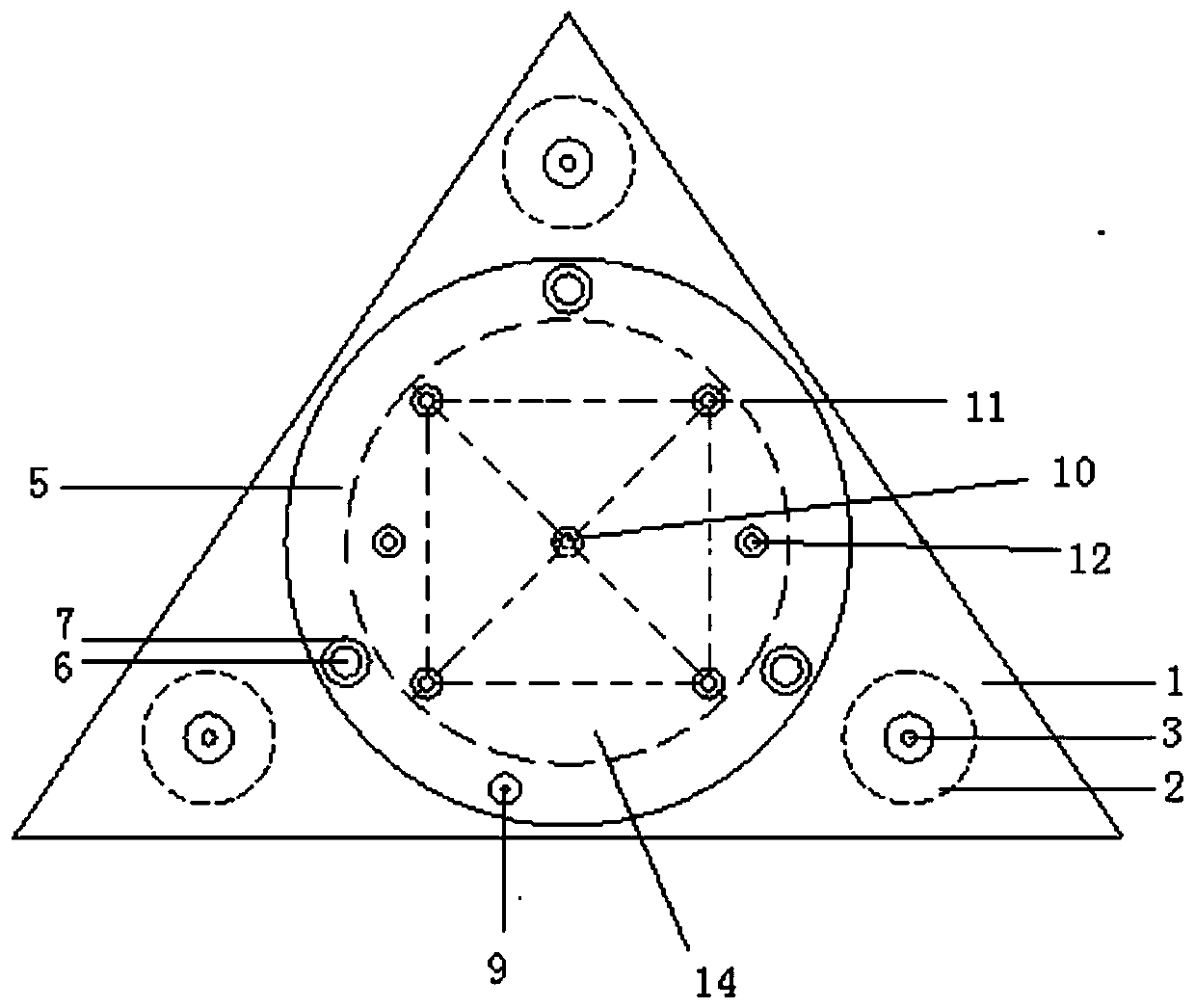
[0048] Step 1: According to the set position, use the total station to measure and position the point, determine the fixed point on the basis of the surrounding of the drill hole, and fix the positioning nail at the fixed point.

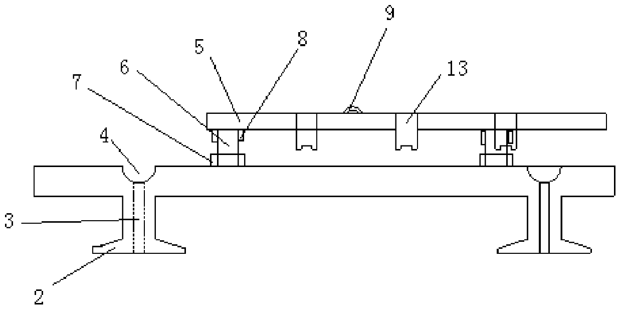
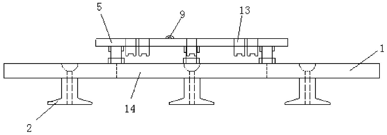
[0049] Step 2: According to the fixed point determined in step 1, insert the positioning nail into the positioning hole of the foot, fix the fixing plate on the foundation around the drilling hole through the foot, and set the fixing plate and the drilling hole coaxially.

[0050] Step 3: Turn the screw, the screw moves along its own axis, drives the support plate for leveling, observe the position of the bubble in the bubble level at any time, and turn the corresponding screw until the bubble in the bubble level is in the middle position, and the support plate is adjusted to the level state.

[0051] Step 4: Start...


PUM


Abstract

The invention relates to a drilling depth and verticality measuring device and a using method thereof. The device comprises a fixing plate, wherein the fixing plate is provided with a plurality of fixing pieces, the fixing plate can be fixedly connected with a foundation through the fixing pieces and is coaxially arranged with a drilling hole, a supporting plate coaxially arranged with the fixingplate is arranged on the fixing plate, a leveling piece is arranged between the fixing plate and the supporting plate, the leveling piece is used for adjusting the level of the supporting plate, a plurality of laser distance measuring devices are mounted on the supporting plate, the laser emitting ends and the receiving ends of the laser distance measuring devices are arranged towards one side ofthe fixing plate, and holes for laser lines emitted by the laser distance measuring devices to pass through are formed in the fixing plate. The measuring device can accurately measure the depth and the verticality of a drilling hole.

Description

technical field [0001] The invention relates to the technical field of underground engineering technology, in particular to a drilling depth and verticality measuring device and a use method. Background technique [0002] The subway station is composed of two parts, the enclosure structure and the main structure. During on-site construction, the enclosure structure should be constructed first, followed by the main structure, and finally the auxiliary structures (entrances, wind pavilions). The general form of the enclosure structure of the subway project is: Enclosure pile or ground connection wall structure; when the subway enclosure structure is constructed with cast-in-place piles or prefabricated piles, it is necessary to carry out the drilling operation of rotary drilling rig and long auger drilling rig first, and then carry out the lifting of reinforcement cage or prefabricated pile structure, and finally The pile-forming process of pouring concrete or cement soil; amo...

Claims


Application Information

Patent Timeline
Patent Type & Authority Applications(China)
IPC IPC(8): E21B47/04E21B47/022
CPCE21B47/022E21B47/04
Inventor 邢慧堂李强种记鑫
Owner JINAN RAILWAY TRANSPORT GRP CO LTD
Learn More