A mechanized and efficient steel pipe paint dyeing device and its application method
A kind of high-efficiency technology for steel pipes, which can be applied to devices and coatings that apply liquid to the surface.
- Summary
- Abstract
- Description
- Claims
- Application Information
AI Technical Summary
Problems solved by technology
Method used
Image
Examples
Embodiment 1
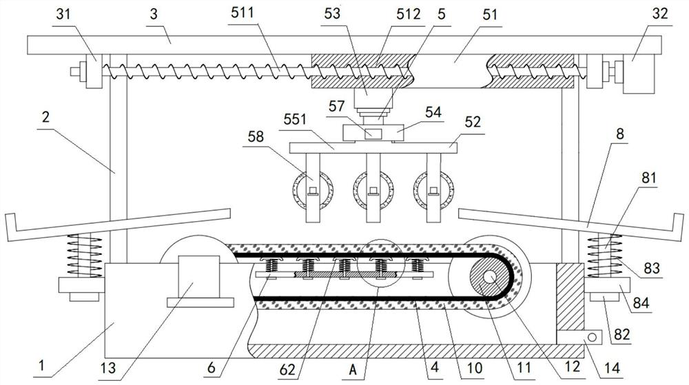
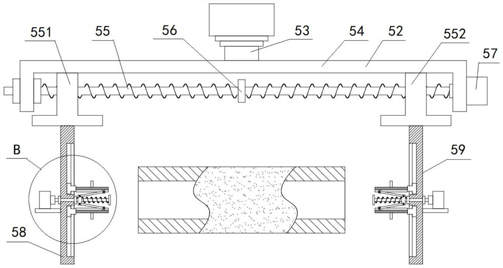
[0099] A mechanized and efficient paint dyeing device for steel pipes, the paint dyeing device includes a square paint tank 1, a bracket 2 and a top plate 3, the top of the square paint tank 1 is fixedly connected to the bottom of the top plate 3 through the bracket 2; Two rollers 11 are arranged symmetrically inside the tank 1, and the middle part of the rollers 11 is provided with a roller rotating shaft 12. The outside of the two rollers 11 is provided with a transmission belt 4, and the outer surface of the transmission belt 4 is covered with a paint sponge 10; the outside of the square paint tank 1 is fixed with a transmission motor 13, and the output of the transmission motor 13 The shaft is driven and matched with the roller shaft 12 of a roller 11; a steel pipe clamping device 5 is arranged between the square paint tank 1 and the top plate 3; the steel pipe clamping device 5 includes a moving assembly 51 and a clamping assembly 52; The moving assembly 51 includes a gui...
Embodiment 2
[0107] Embodiment 2 is basically the same as Embodiment 1, and its difference is:
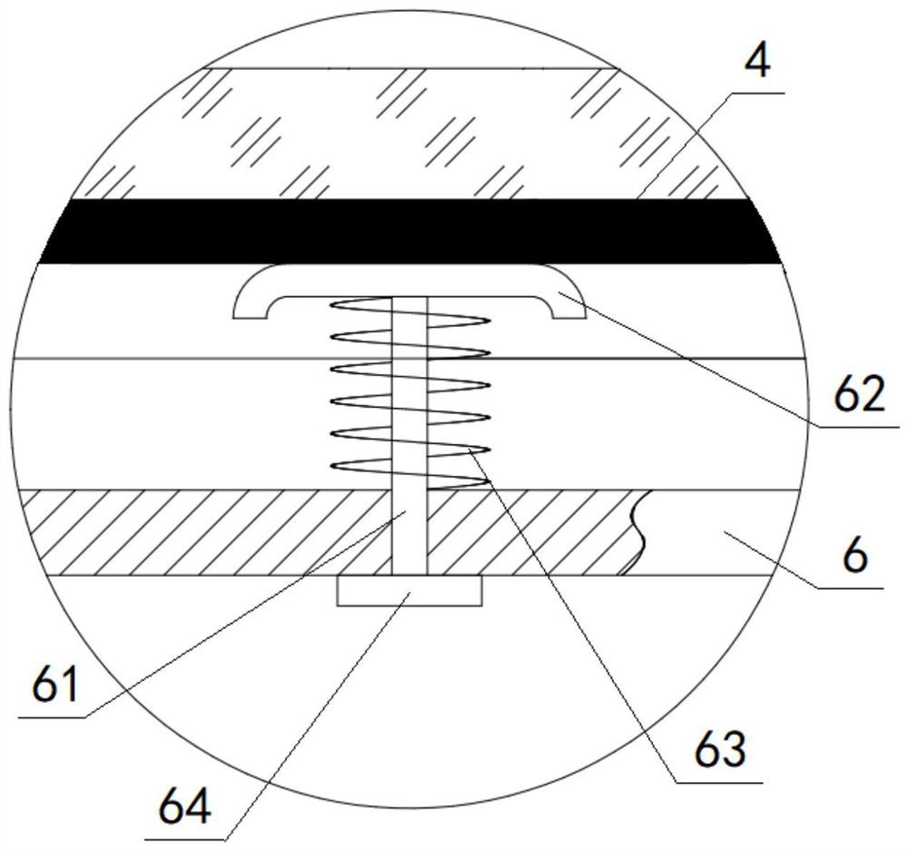
[0108] A horizontal plate 6 is arranged between the two rollers 11, and the horizontal plate 6 is located in the middle of the ring-shaped transmission belt 4, and the horizontal plate 6 is fixedly connected with the inner wall of the square paint tank 1. On the horizontal plate 6 A plurality of elastic supporting mechanisms are arranged at equal intervals; the elastic supporting mechanism includes a guide rod 61, a supporting plate 62, a spring 63 and a limit block 64, and the lower end of the guide rod 61 is fixedly connected with the limit block 64, The upper end of the guide rod 61 passes through the horizontal plate 6 and is fixedly connected with the supporting plate 62. The spring 63 is sleeved on the outside of the guide rod 61. The top of the spring 63 is connected with the bottom of the supporting plate 62, and the bottom of the spring 63 Be connected with the top of horizontal plate ...
Embodiment 3
[0111] Embodiment 3 is basically the same as Embodiment 2, and its difference is:
[0112] The bottom of the shaped paint tank 1 is provided with a paint discharge pipe 14 communicating with it, and the paint discharge pipe 14 is provided with a paint discharge valve; both sides of the square paint tank 1 are respectively provided with a steel pipe bracket 8, The bottom of the steel pipe bracket 8 is fixedly connected with the upper end of the guide post 81, and the lower end of the guide post 81 passes through the mounting plate 84 fixed on the side of the square paint tank 1 and is fixedly connected with the bracket stopper 82. A bracket spring 83 is sleeved on the outside of the guide post 81 , the top of the bracket spring 83 is connected to the bottom of the steel pipe bracket 8 , and the bottom of the bracket spring 83 is connected to the top of the mounting plate 84 .
PUM
 Abstract
Description
Claims
Application Information
 - R&D
- Intellectual Property
- Life Sciences
- Materials
- Tech Scout
- Unparalleled Data Quality
- Higher Quality Content
- 60% Fewer Hallucinations
Browse by: Latest US Patents, China's latest patents, Technical Efficacy Thesaurus, Application Domain, Technology Topic, Popular Technical Reports.
© 2025 PatSnap. All rights reserved.Legal|Privacy policy|Modern Slavery Act Transparency Statement|Sitemap|About US| Contact US: help@patsnap.com


