
Oxygen generator solenoid valve control structure and control system thereof

A control structure and solenoid valve technology, applied in valve details, valve devices, inorganic chemistry, etc., can solve problems such as the greater influence of the altitude of the oxygen generator, the impact on the efficiency of the oxygen generation system, and the failure of the oxygen generation system to work normally. Achieve the effect of improving work efficiency

Pending Publication Date: 2021-11-26
HEFEI MEILING PURIFYING EQUIP
View PDF0 Cites 1 Cited by
  • Summary
  • Abstract
  • Description
  • Claims
  • Application Information

AI Technical Summary

Problems solved by technology

[0003] However, the oxygen concentrator controlled by the above method is greatly affected by the altitude of the operating environment, because at different altitudes, the gas output of the air compressor in the oxygen concentrator is different in the same time period, which leads to the molecular sieve in the oxygen concentrator system. The conversion of adsorption and desorption is carried out under the optimal adsorption pressure, which will affect the working efficiency of the whole oxygen production system. Control System

Method used


Image

  • Oxygen generator solenoid valve control structure and control system thereof
  • Oxygen generator solenoid valve control structure and control system thereof
  • Oxygen generator solenoid valve control structure and control system thereof

Examples


Embodiment 1

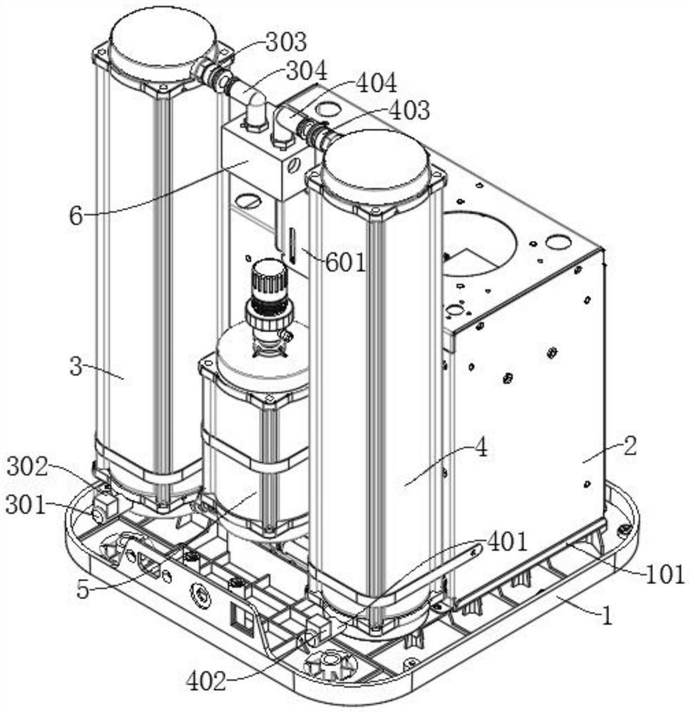
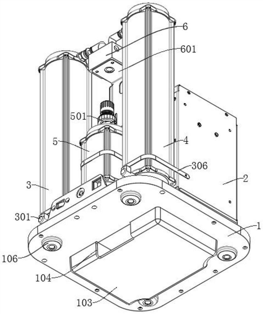
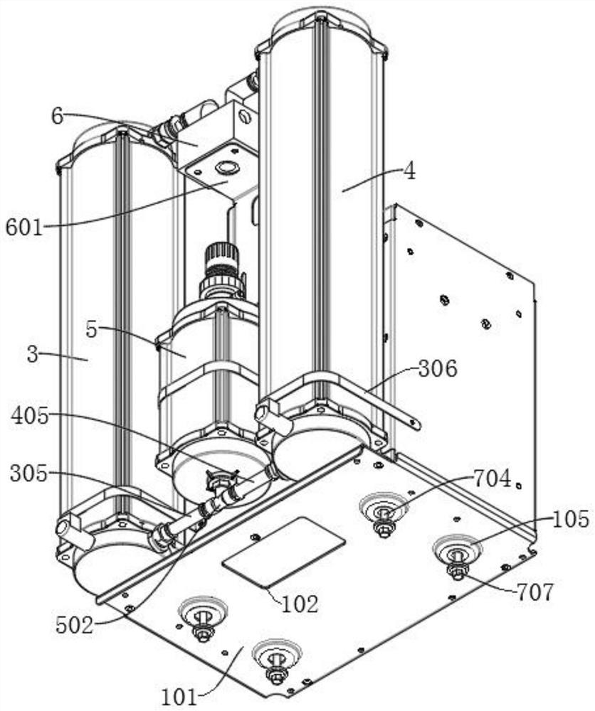
[0035] refer to Figure 1-Figure 5 , a solenoid valve control structure for an oxygen generator, including a base 1 and a housing 2, the housing 2 is connected to the base 1, and the housing 2 is connected with an air compressor body 7 for oxygen production operation, and a molecular sieve is also provided Tower A3 and molecular sieve tower B4, the bottoms of molecular sieve tower A3 and molecular sieve tower B4 are respectively equipped with oxygen output tube A301 and oxygen output tube B401, and oxygen output tube A301 and oxygen output tube B401 are respectively equipped with air pressure sensor A302 and The air pressure sensor B402, by setting the air pressure sensor A302 and the air pressure sensor B402 at the bottom, controls the operation of the solenoid valve 6 of the system by sampling the pressure of the oxygen output end, and improves the output efficiency of oxygen; the system solenoid valve 6 is arranged on the top of the housing 2 , the system solenoid valve 6 i...

Embodiment 2

[0040] refer to Figure 4 and Figure 5 , a solenoid valve control structure for an oxygen generator, including a base 1 and a housing 2, the housing 2 is connected to the base 1, and the housing 2 is connected with an air compressor body 7 for oxygen production operation, and a molecular sieve is also provided Tower A3 and molecular sieve tower B4, the bottoms of molecular sieve tower A3 and molecular sieve tower B4 are respectively equipped with oxygen output tube A301 and oxygen output tube B401, and oxygen output tube A301 and oxygen output tube B401 are respectively equipped with air pressure sensor A302 and The air pressure sensor B402, by setting the air pressure sensor A302 and the air pressure sensor B402 at the bottom, controls the operation of the solenoid valve 6 of the system by sampling the pressure of the oxygen output end, and improves the output efficiency of oxygen; the system solenoid valve 6 is arranged on the top of the housing 2 , the system solenoid val...

Embodiment 3

[0044] refer to figure 1 , a solenoid valve control structure for an oxygen generator, including a base 1 and a housing 2, an air compressor body 7 is connected to the housing 2, a molecular sieve tower A3 and a molecular sieve tower B4 are connected to the housing 2, and the molecular sieve tower A3 and the molecular sieve The bottom of the tower B4 is respectively provided with an oxygen output pipe A301 and an oxygen output pipe B401, and an air pressure sensor A302 and an air pressure sensor B402 are respectively arranged on the oxygen output pipe A301 and the oxygen output pipe B401; The solenoid valve 6, the system solenoid valve 6 is connected to the air compressor body 7 through pipelines, the molecular sieve tower A3 and the molecular sieve tower B4 are connected to the system solenoid valve 6, the air pressure sensor A302 and the air pressure sensor B402 are connected to the system solenoid valve 6 signal; A filter 5 is also connected to the body 2, and an air inlet ...


PUM


Abstract

The invention discloses an oxygen generator electromagnetic valve control structure and a control system thereof, and belongs to the field of oxygen generators. The control structure comprises a base and a shell, wherein an air compressor body is connected into the shell, a molecular sieve tower A and a molecular sieve tower B are connected to the shell, and an oxygen output pipe A and an oxygen output pipe B are arranged at the bottom of the molecular sieve tower A and the bottom of the molecular sieve tower B respectively. An air pressure sensor A and an air pressure sensor B are respectively arranged on the oxygen output pipe A and the oxygen output pipe B; a system electromagnetic valve is arranged at the top of the shell, and the air pressure sensor A and the air pressure sensor B are both in signal connection with the system electromagnetic valve. According to the invention, molecular sieves in the molecular sieve tower A or the molecular sieve tower B can be controlled to always perform corresponding actions at the optimal adsorption or desorption pressure, the working efficiency of an oxygen generation system can be effectively improved by more than 15%, and meanwhile, the problem that the current oxygen generator is influenced by the altitude of the operating environment is greatly improved.

Description

technical field [0001] The invention relates to the technical field of oxygen generators, in particular to an oxygen generator solenoid valve control structure and a control system thereof. Background technique [0002] Oxygen concentrator is a kind of machine for producing oxygen. Its principle is to use air separation technology to first compress the air with high density and then use the difference in the condensation point of each component in the air to separate the gas and liquid at a certain temperature. , obtained by further rectification. At present, the system solenoid valves of small medical oxygen generators, the working hours of molecular sieve tower A and molecular sieve tower B are controlled by preset time, that is, by setting molecular sieve tower A and molecular sieve tower B in the MCU. The single tower intake time and the common intake time of the molecular sieve tower B are used to control the working sequence of the solenoid valve of the system to contr...

Claims


Application Information

Patent Timeline
Patent Type & Authority Applications(China)
IPC IPC(8): B01D53/047F16K31/06F16K37/00C01B13/02
CPCB01D53/047C01B13/0259F16K31/06F16K37/0075
Inventor 周志园
Owner HEFEI MEILING PURIFYING EQUIP
Learn More