
Nitrogen generation control method for refrigerating and freezing equipment and refrigerating and freezing equipment

A technology of refrigeration and freezing equipment and a control method, which is applied in the field of refrigeration and freezing equipment, can solve the problems of affecting service life, increasing operating time, and high cost, and achieves the effects of avoiding working hours, increasing load, and increasing noise

Active Publication Date: 2017-01-04
HAIER SMART HOME CO LTD
View PDF6 Cites 1 Cited by
  • Summary
  • Abstract
  • Description
  • Claims
  • Application Information

AI Technical Summary

Problems solved by technology

[0004] In the prior art, the concentration sensor can be used to control nitrogen production according to the established procedure, but there are the following disadvantages: the cost of the concentration sensor is very high, and even if its opening frequency is low, the service life is about two years, and it cannot be used in cold storage. Long-term use on refrigeration equipment
However, this control method cannot accurately control the nitrogen production process, which may increase the extra working time of the nitrogen production device, and increase the operating time of the nitrogen production device at high temperature, which will affect its service life; the cavity where the nitrogen production device is located High temperature will also have adverse effects on other components

Method used


Image

  • Nitrogen generation control method for refrigerating and freezing equipment and refrigerating and freezing equipment
  • Nitrogen generation control method for refrigerating and freezing equipment and refrigerating and freezing equipment
  • Nitrogen generation control method for refrigerating and freezing equipment and refrigerating and freezing equipment

Examples


Embodiment Construction

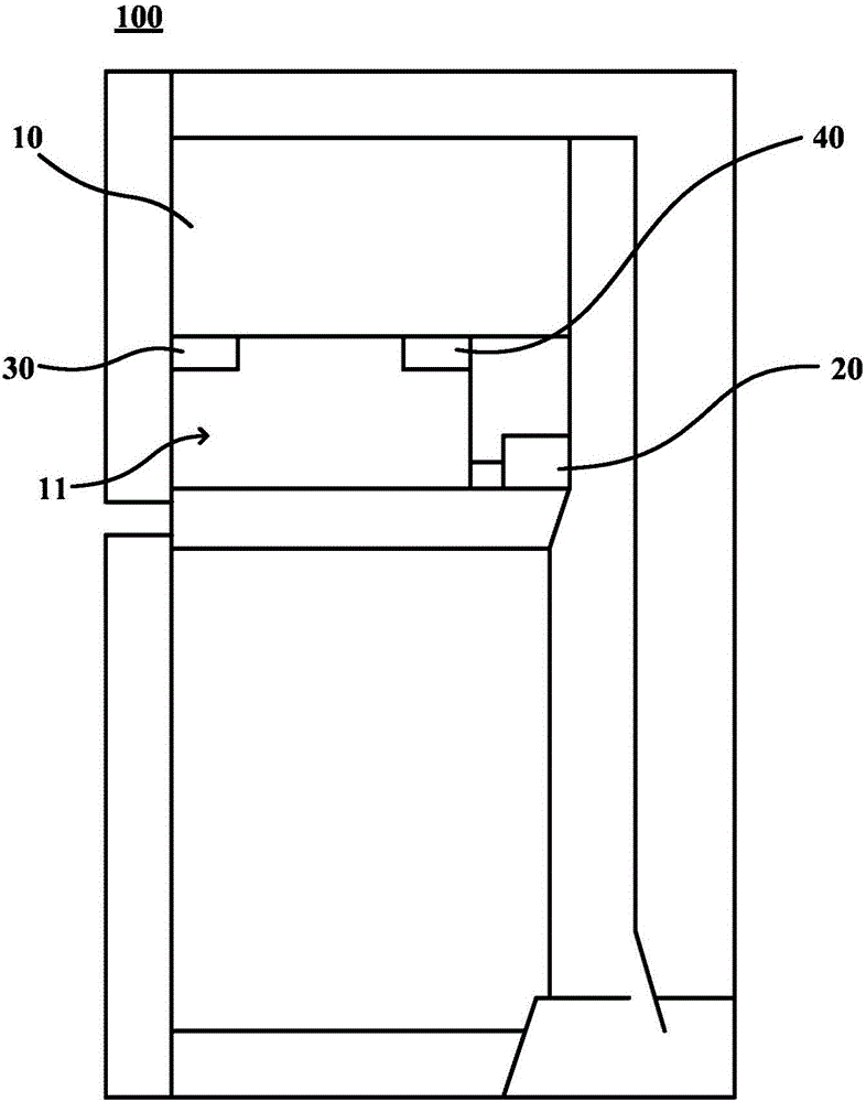
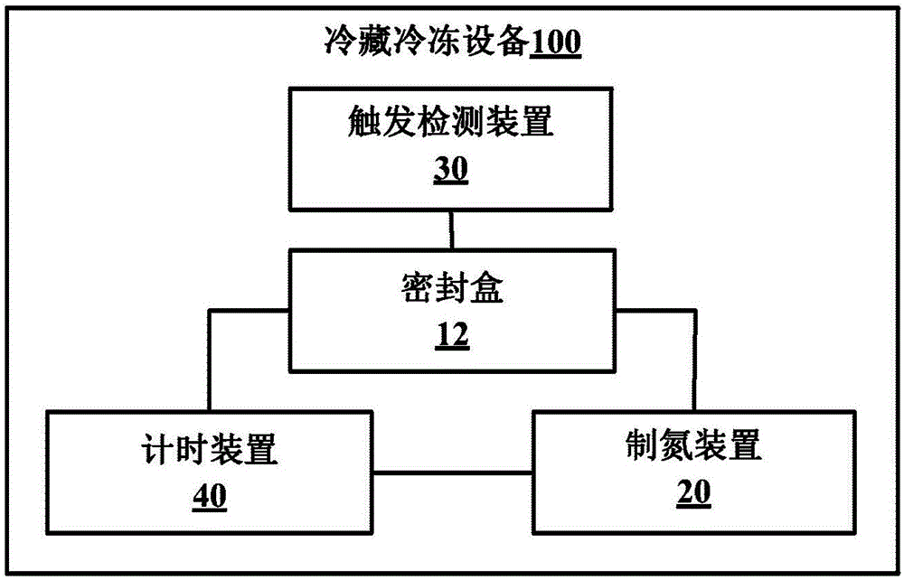
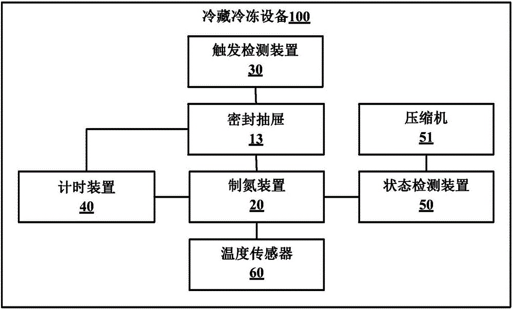
[0026] This embodiment first provides a refrigerating and freezing device 100, figure 1 is a schematic diagram of a refrigerating and freezing device 100 according to an embodiment of the present invention, figure 2 is a schematic block diagram of a refrigerating and freezing device 100 according to an embodiment of the present invention. The refrigerating and freezing equipment 100 may be a refrigerator, a freezer, and the like.

[0027] The refrigerating and freezing equipment 100 of this embodiment has a storage compartment 10, and a sealed space 11 is arranged inside the storage compartment 10. In this embodiment, a sealed box 12 is arranged in the storage compartment 10, and the above-mentioned sealed space 11 can be formed by The sealed box 12 is defined, and in some optional embodiments, the above-mentioned sealed space 11 may also be defined by a sealed drawer, a sealed tank, a sealed box, and the like. The refrigerating and freezing equipment 100 of this embodiment...


PUM


Abstract

The invention provides a nitrogen generation control method for refrigerating and freezing equipment and the refrigerating and freezing equipment. The nitrogen generation control method for the refrigerating and freezing equipment comprises the steps that trigger signals of opening and closing a sealed space are detected; it is determined that the sealed space is opened according to the trigger signals, and after the sealed space is closed for first preset time, a nitrogen generation device is controlled to operate for second preset time so as to provide nitrogen for the sealed space; and when no trigger signal is detected in third preset time after the nitrogen generation device completes nitrogen generation, the nitrogen generation device is controlled to operate for fourth preset time so as to compensate for nitrogen naturally leaked out of the sealed space. Through the scheme, the situation that a concentration sensor is used for measuring the oxygen concentration in the sealed space so that the working state of the nitrogen generation device can be controlled is avoided, the cost is reduced, the two states, namely the opened state and the unopened state, of the sealed space are distinguished, accurate control is conducted, unnecessary working time of the nitrogen generation device is not increased, and the refrigerator energy consumption is reduced.

Description

technical field [0001] The invention relates to the field of item storage, in particular to a nitrogen production control method for refrigeration and freezing equipment and the refrigeration and freezing equipment. Background technique [0002] With the development of society and the improvement of people's living standards, and people's pace of life is getting faster and faster, people often buy a large number of items placed in various refrigeration and freezing equipment, but for leafy vegetables and melon and fruit foods, refrigeration and freezing The low temperature in the appliance's storage compartment will not only wrinkle and blotch the skin of these foods, but also affect their original taste and nutrition. [0003] Nitrogen, as a colorless, non-toxic, odorless inert gas, has been widely used in the field of food preservation. Filling the storage compartment of refrigeration and freezing equipment with nitrogen to balance the carbon dioxide and oxygen in it can e...

Claims


Application Information

Patent Timeline
IPC IPC(8): F25D29/00
CPCF25D29/003F25D2600/06
Inventor 刘浩泉姜波王丽燕朱小兵辛若武
Owner HAIER SMART HOME CO LTD
Learn More