Camera test equipment and camera imaging test method

A technology for testing equipment and cameras, applied in image communication, television, electrical components, etc., can solve the problems of inability to adjust the level of the camera and the imaging angle, low efficiency of the testing process, and low detection accuracy, and achieves a simple and convenient testing method. Improve the efficiency of the test and the accurate effect of the detected data

Pending Publication Date: 2021-11-23
上海研鼎信息技术有限公司
View PDF0 Cites 4 Cited by
  • Summary
  • Abstract
  • Description
  • Claims
  • Application Information

AI Technical Summary

Problems solved by technology

[0004] The object of the present invention is to provide a camera testing device and a camera imaging testing method to solve the problem that the testing device in the prior art cannot adjust the level and imaging angle of the camera, thereby resulting in low detection accuracy and low efficiency of the test process

Method used


Image

  • Camera test equipment and camera imaging test method
  • Camera test equipment and camera imaging test method
  • Camera test equipment and camera imaging test method

Examples


Embodiment 1

[0054] This embodiment provides a camera testing device, which can be used to test the imaging of the camera 4 .

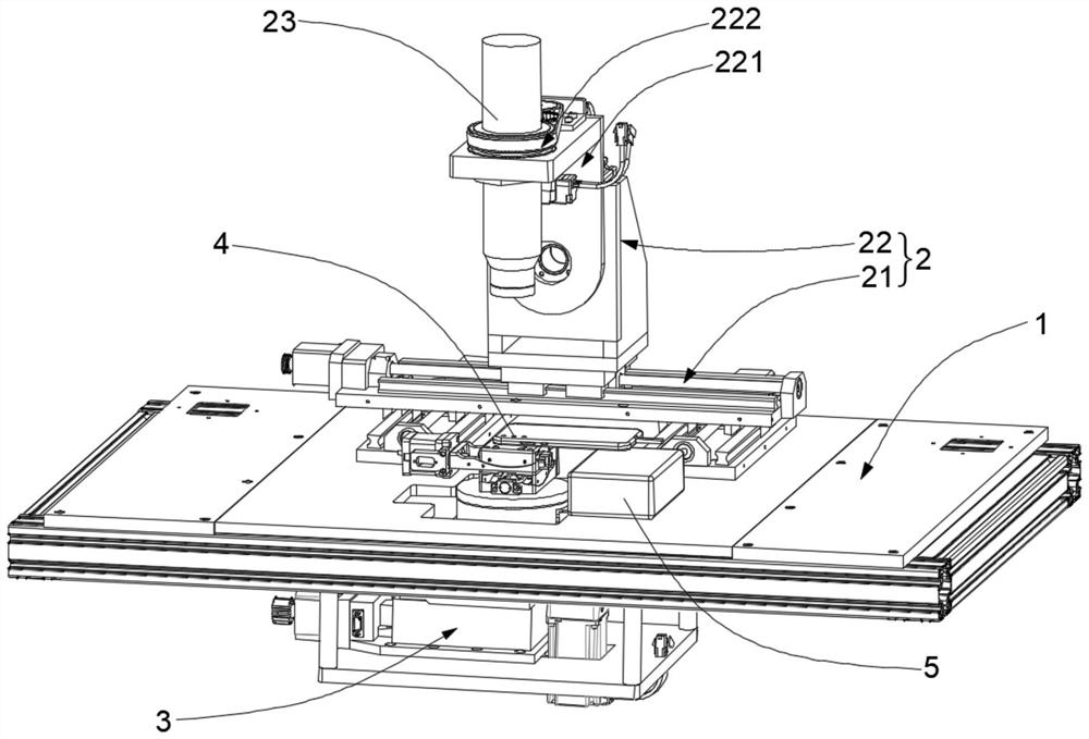
[0055] Such as figure 1 As shown, the camera testing device includes a support platform 1 , a collimator 23 , a first adjustment module 2 , a second adjustment module 3 and an image receiving assembly 5 . The first adjustment module 2 includes an XY moving platform 21 arranged on the support platform 1 and a rotating module 22 arranged at the driving end of the XY moving platform 21. The XY moving platform 21 can be used to adjust the position of the rotating module 22 in the horizontal plane. At the same time, the driving end of the rotating module 22 is connected to the collimator 23 , and the position of the collimator 23 in the horizontal plane can be adjusted through the XY moving platform 21 to facilitate the subsequent detection of the imaging of the camera 4 . Wherein, the collimator 23 includes a collimator body, a map card and a light source assembly, a...

Embodiment 2

[0075] This embodiment also provides a camera testing device, which can also be used to test the imaging of the camera 4 .

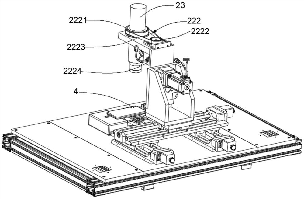
[0076] The camera testing equipment provided in this embodiment is basically the same as the camera testing equipment in Embodiment 1, the difference is that in this embodiment, the carrying assembly 221 includes a moving frame 2211 , a swinging frame 2212 and a second rotating drive assembly 2213 . Such as Figure 4~5 As shown, the moving frame 2211 is arranged on the driving end of the XY moving platform 21, the second rotating drive assembly 2213 is arranged on the moving frame 2211, and the output end of the second rotating driving assembly 2213 is fixedly connected to the swing frame 2212 for driving the swing The frame 2212 swings in the vertical plane. At the same time, the collimator 23 and the first rotating drive assembly 222 are arranged on the swing frame 2212, so that the collimator 23 is also vertically rotated by the swing frame 2212 in th...


PUM


Abstract

The invention relates to the technical field of camera testing, and particularly discloses camera testing equipment and a camera imaging testing method. The camera testing device comprises a supporting platform, a first adjusting module, a second adjusting module and an image receiving assembly. The first adjusting module comprises an XY moving platform and a rotating module arranged at the driving end of the XY moving platform, and the driving end of the rotating module is connected with the collimator; the second adjustment module comprises a moving module and a horizontal fine adjustment module arranged at the driving end of the moving module, and the camera is supported on the horizontal fine adjustment module; and the image receiving assembly is used for receiving image signals shot by the camera. Under the condition that the angle of the camera does not need to be adjusted, the imaging angle of the camera during image card shooting can be adjusted by adjusting the rotating module. Meanwhile, the horizontal precision of the camera adjusted by the horizontal fine adjustment module is high, so that the data detected by the method is accurate, the adjustment process is simple and convenient, and the test efficiency is improved.

Description

technical field [0001] The invention relates to the technical field of camera testing, in particular to a camera testing device and a camera imaging testing method. Background technique [0002] Camera, also known as computer camera, computer eye, electronic eye, etc., is a video input device, which is widely used in video shooting, photographing and real-time monitoring. In daily life, people often use devices such as mobile phones or computers with cameras, and the requirements for the imaging quality of cameras are getting higher and higher. [0003] In the production process of the camera, it is necessary to carry out quality inspection, but in the existing test equipment, the picture card and the light source are generally installed inside the collimator, and then the camera is used to capture the images of the collimator under different fields of view. Data, to detect the imaging quality of the camera, the test process does not need to be equipped with test charts of ...

Claims


Application Information

Patent Timeline
Patent Type & Authority Applications(China)
IPC IPC(8): H04N17/00
CPCH04N17/002
Inventor 侯晓凯徐方达
Owner 上海研鼎信息技术有限公司
Why Eureka
Try Eureka