
Control method and terminal equipment of conversion circuit

A technology for converting circuits and control methods, which is applied to control/regulating systems, converting DC power input to DC power output, electrical components, etc. Work and other problems, to achieve the effect of convenient power limiting or current limiting, good dynamic indicators, and preventing excessive input power

Active Publication Date: 2022-08-09
KEHUA DATA CO LTD +1
View PDF5 Cites 0 Cited by
  • Summary
  • Abstract
  • Description
  • Claims
  • Application Information

AI Technical Summary

Problems solved by technology

Moreover, the output voltage of the circuit is usually controlled by the inverter of the subsequent stage, which is not controlled by itself and has a certain amount of fluctuation
[0006] In this case, the control process of the circuit must not only match the input voltage when the battery power is maximized, but also match the voltage fluctuation at the output. In order to make the circuit work stably, the input voltage range is limited.
For example, in the case of input high voltage or output low voltage, the circuit is prone to It is difficult to work stably under certain working conditions, the output voltage range of the fuel cell is limited, and it is impossible to realize the wide-range operation of the fuel cell

Method used

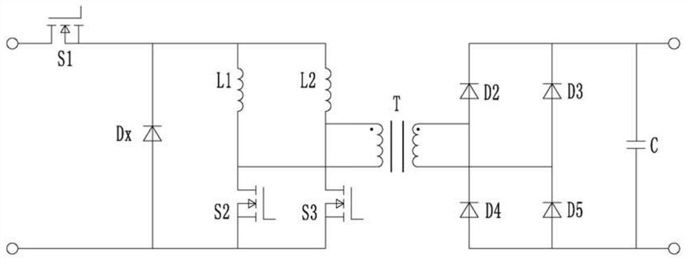

Image

  • Control method and terminal equipment of conversion circuit
  • Control method and terminal equipment of conversion circuit
  • Control method and terminal equipment of conversion circuit

Examples


Embodiment Construction

[0033] The technical solutions in the embodiments of the present invention will be clearly and completely described below with reference to the accompanying drawings in the embodiments of the present invention. Obviously, the described embodiments are preferred embodiments of the present invention and should not be construed to exclude other embodiments. Based on the embodiments of the present invention, all other embodiments obtained by those of ordinary skill in the art without creative efforts fall within the protection scope of the present invention.

[0034] In the claims, description and the above drawings of the present invention, unless otherwise clearly defined, the terms "first", "second" or "third" are used to distinguish different objects, rather than used for Describe a specific order.

[0035] In the claims, description and the above drawings of the present invention, if the terms "including", "having" and their modifications are used, the intention is to "inclu...


PUM


Abstract

The invention discloses a control method and a terminal device for a conversion circuit. The control method includes acquiring a first target parameter of the circuit used to characterize a target voltage gain of the circuit; when the first target parameter is greater than or less than a first threshold value When the first strategy or the second strategy is used to control the switches of the step-down module and the boost module respectively, so that the actual voltage gain of the circuit matches the target voltage gain; wherein the first strategy is to control the first The switch works with the first duty cycle, and both the second switch and the third switch work higher than the second duty cycle; the second strategy is to control the first switch to work lower than the first duty cycle, and the second switch and the third switch work All three switches operate at the second duty cycle. The control method of the present invention makes the corresponding conversion circuit suitable for accepting a wide range of voltage input on the basis of stable operation, fully utilizes the input power supply and can match the fluctuation of the output terminal, and has a wide application range.

Description

technical field [0001] The present invention relates to the technical field of conversion circuit control, in particular to a control method and terminal equipment of a conversion circuit. Background technique [0002] Existing dual-inductor current mode push-pull circuits such as figure 1 As shown, the characteristics of this circuit are: in order to provide a freewheeling path for the inductor current, the duty ratios of the switches S1 and S2 need to have an overlapping area, that is, the duty ratios of the switches S1 and S2 are greater than 0.5. Generally speaking, as a DC / DC boost topology, the traditional control method is to control it as a voltage source and output voltage stably. [0003] In addition, according to the steady-state equation in continuous mode, the voltage gain (ratio of output voltage to input voltage) of the circuit in steady-state operation and the duty cycle of the two switches, transformer turns ratio and other parameters have the following rel...

Claims


Application Information

Patent Timeline
Patent Type & Authority Patents(China)
IPC IPC(8): H02M3/335
CPCH02M3/33569Y02E60/50
Inventor 陈文佳吴庆彬陈钦鸿罗春李
Owner KEHUA DATA CO LTD
Learn More