IGBT (Insulated Gate Bipolar Translator) driving circuit and electronic equipment

A driving circuit and circuit technology, applied in the direction of electrical components, output power conversion devices, etc., can solve the problem of not necessarily guaranteeing the reliable driving of IGBTs, and achieve the effect of saving hardware resources

Pending Publication Date: 2021-11-23
GREE ELECTRIC APPLIANCES INC
View PDF6 Cites 0 Cited by
  • Summary
  • Abstract
  • Description
  • Claims
  • Application Information

AI Technical Summary

Problems solved by technology

[0005] The main purpose of this application is to provide an IGBT drive circuit and electronic equipment to solve the problem in the prior art that the drive current of the push-pull drive circuit does not necessarily guarantee the reliable drive of the IGBT

Method used


Image

  • IGBT (Insulated Gate Bipolar Translator) driving circuit and electronic equipment
  • IGBT (Insulated Gate Bipolar Translator) driving circuit and electronic equipment
  • IGBT (Insulated Gate Bipolar Translator) driving circuit and electronic equipment

Examples


Embodiment Construction

[0023] It should be pointed out that the following detailed description is exemplary and intended to provide further explanation to the present application. Unless defined otherwise, all technical and scientific terms used herein have the same meaning as commonly understood by one of ordinary skill in the art to which this application belongs.

[0024] It should be noted that the terminology used here is only for describing specific implementations, and is not intended to limit the exemplary implementations according to the present application. As used herein, unless the context clearly dictates otherwise, the singular is intended to include the plural, and it should also be understood that when the terms "comprising" and / or "comprising" are used in this specification, they mean There are features, steps, operations, means, components and / or combinations thereof.

[0025] It will be understood that when an element such as a layer, film, region, or substrate is referred to as ...


PUM


Abstract

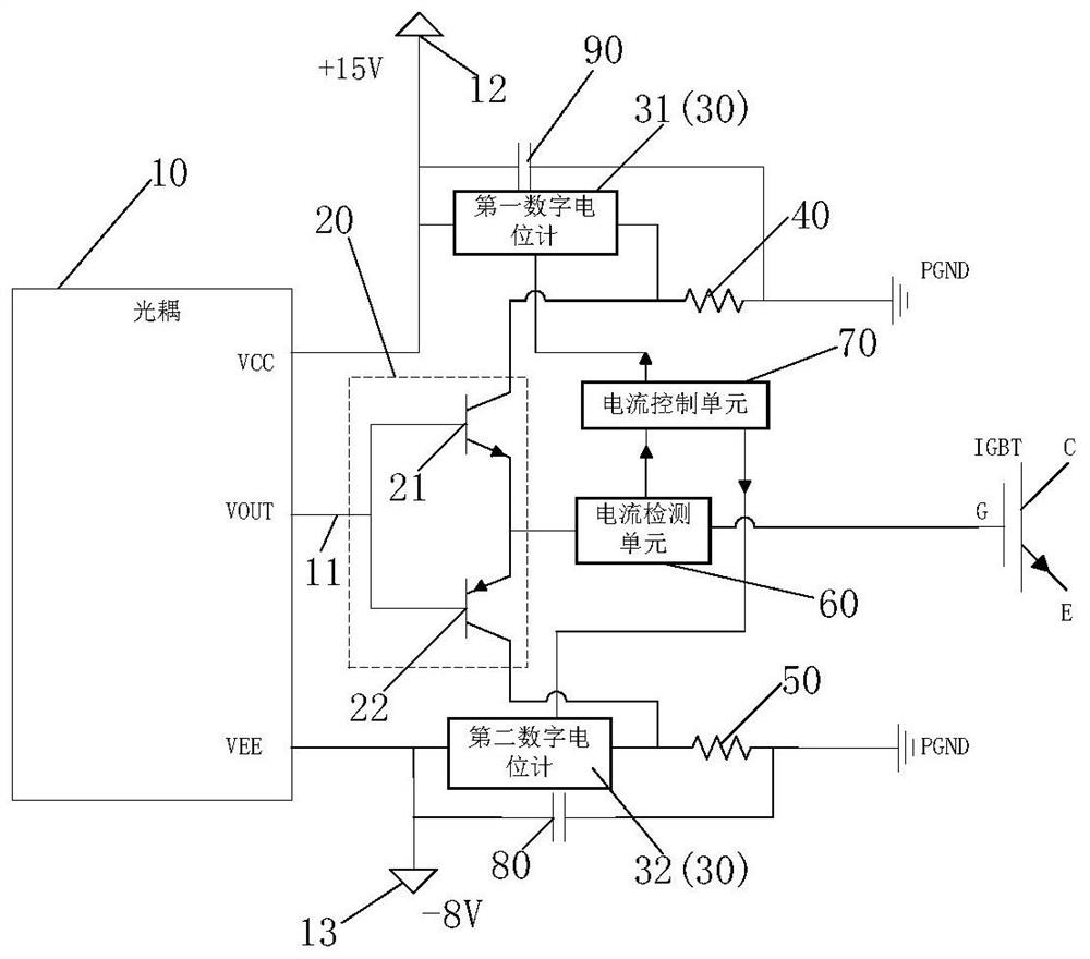
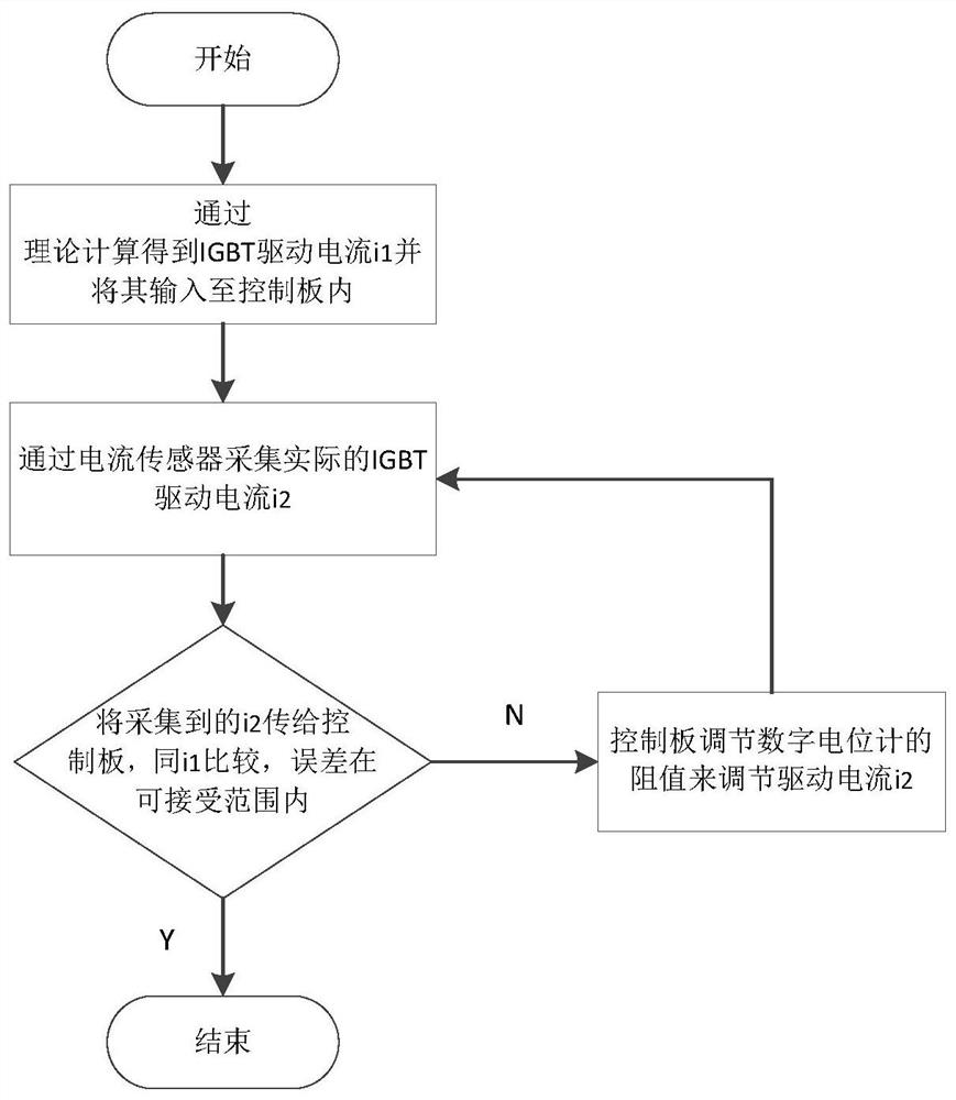
The invention provides an IGBT (Insulated Gate Bipolar Translator) driving circuit and electronic equipment. The circuit comprises an optocoupler unit; a push-pull unit which is electrically connected with the optocoupler unit; and a resistance adjustable unit which is electrically connected with the optocoupler unit and the push-pull unit. The magnitude of the output current of the push-pull unit is adjusted in real time by adjusting the resistance value of the resistance adjustable unit, and the output current of the push-pull unit is the gate drive current of the IGBT. By adjusting the resistance value of the resistance adjustable unit, the magnitude of the output current of the push-pull unit can be adjusted, and driving of different IGBTs can be ensured. The problem that the driving current output by the push-pull unit in the prior art is not adjustable is solved, and reliable driving of an IGBT is ensured. Therefore, the driving circuit can adapt to IGBTs with different rated currents. Hardware resources are saved.

Description

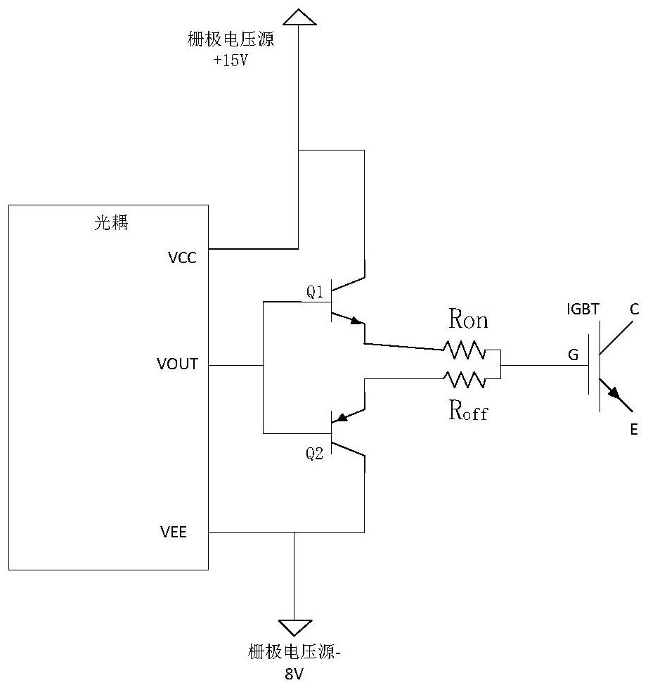
technical field [0001] The present application relates to the field of IGBT driving, in particular, to an IGBT driving circuit and electronic equipment. Background technique [0002] In the prior art, most IGBT drive circuits use high-speed optocouplers to achieve isolation. The advantage is that the transmission delay is small and common-mode interference can be well suppressed. However, the output current of optocouplers currently on the market is generally small (basically No more than 4A), not suitable for driving large current IGBT (IGBT above 150A), some manufacturers have optocouplers with maximum output current of 6A, 8A, 10A, but generally the price is high, so now drive large current For IGBT, two transistors are added to the output stage of the optocoupler to form a complementary emitter output circuit (push-pull circuit), which is used to amplify the output current of the optocoupler to meet the drive of the high-current IGBT. [0003] Such as figure 1 As shown...

Claims


Application Information

Patent Timeline
Patent Type & Authority Applications(China)
IPC IPC(8): H02M1/088H02M1/092
CPCH02M1/088H02M1/092
Inventor 张家梁谭章德刘旭龙郑培杰李通张敏
Owner GREE ELECTRIC APPLIANCES INC
Why Eureka
Try Eureka