
Gas-liquid two-phase flow phase interface density calculation method, device and equipment and storage medium

A gas-liquid two-phase flow and calculation method technology, applied in computer-aided design, calculation, design optimization/simulation, etc., can solve large arbitrary, complex, unknowable problems, achieve high precision, overcome poor applicability, and good The effect of applicability

Pending Publication Date: 2021-11-23
SHANGHAI JIAO TONG UNIV +1
View PDF0 Cites 2 Cited by
  • Summary
  • Abstract
  • Description
  • Claims
  • Application Information

AI Technical Summary

Problems solved by technology

However, this equation considers the change of the volume fraction of each phase in the two-phase flow and the appearance or disappearance of the phase interface density caused by the change of the phase interface structure through the source term, which must be obtained in advance when solving the phase interface density transport equation However, the source term of the phase interface is affected by microscopic parameters such as local flow field curl and turbulence around the bubbles. The current experimental methods still cannot obtain accurate two-phase microscopic flow field structures, especially in medium and high cavitation bubbles. In the case of share, the two-phase flow field structure is extremely complex, and the experiment cannot quantitatively measure the local flow field structure
The existing phase interface density source term models are mostly based on simplified theoretical derivation or bubbly flow experiments with low cavitation fraction. The applicability of the model in the bubbly flow region is acceptable, but it is still not suitable for complex flow patterns such as slug flow and intermittent flow. Not applicable
In addition, when solving the phase interface density transport equation, the inlet boundary condition needs to be given, that is, the inlet phase interface density distribution, but this parameter is still unknown, and the setting of this parameter in the solution process is relatively arbitrary.
Based on the above analysis, it can be seen that the calculation of phase interface density based on the phase interface density transport equation has the problems of narrow range of use of the model and incomplete auxiliary models.

Method used


Image

  • Gas-liquid two-phase flow phase interface density calculation method, device and equipment and storage medium
  • Gas-liquid two-phase flow phase interface density calculation method, device and equipment and storage medium
  • Gas-liquid two-phase flow phase interface density calculation method, device and equipment and storage medium

Examples


Embodiment 1

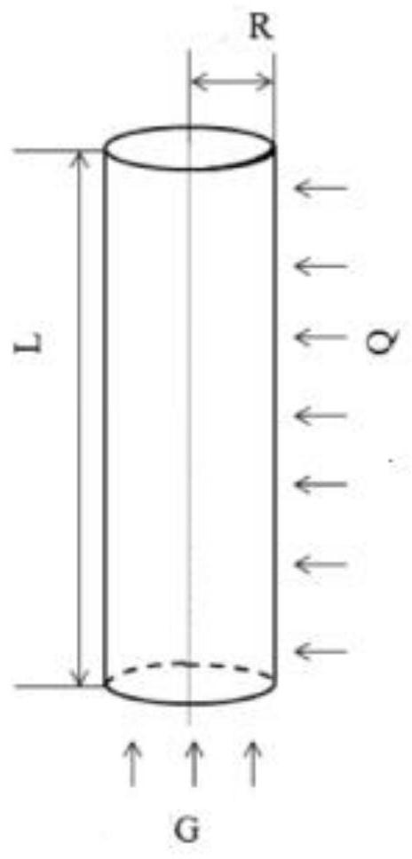
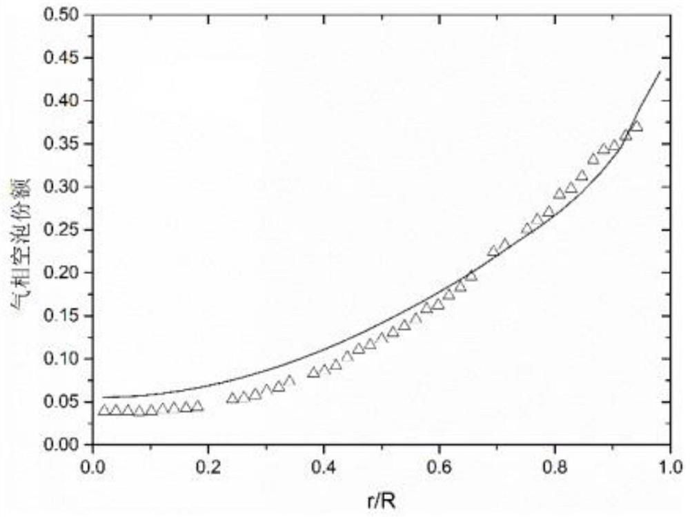
[0050] In order to improve the problems of poor accuracy and poor applicability in the implementation process of the existing technology (algebraic phase interface density model and phase interface density transport equation), this embodiment provides a simple and high-precision phase interface density of gas-liquid two-phase flow The calculation method makes full use of the existing relatively complete drift velocity model to calculate the gas-liquid phase interface density in the complex flow field, and improves the calculation accuracy of the phase interface concentration of complex flow patterns such as slug flow, turbulent flow, and annular flow. It has the characteristics of wide application range, complete model and high precision, and it does not need to give complicated boundary conditions, so the application is relatively simple.

[0051] For details, please refer to figure 1 , the gas-liquid two-phase flow phase interface density calculation method includes the foll...

Embodiment 2

[0085] This embodiment provides a gas-liquid two-phase flow phase interface density calculation device, which is used to study the heat transfer of gas-liquid two-phase flow in thermal and nuclear energy systems. Please refer to Figure 5 , the gas-liquid two-phase flow interface density calculation device includes:

[0086] The flow pattern judgment module 1 is used to obtain the gas-liquid two-phase flow at different positions in the channel under the condition of the current cavity share according to the channel structure and the void fraction in thermal and nuclear energy systems, combined with the corresponding flow pattern diagram flow pattern;

[0087] The velocity calculation module 2 is used to create a corresponding drift velocity model according to the flow pattern of the gas-liquid two-phase flow, and calculate the drift velocity v of the gas-liquid two-phase flow in the channel gj ;

[0088] The drag force calculation module 3 is used to calculate the correspond...

Embodiment 3

[0096] This embodiment provides a device for calculating the interface density of a gas-liquid two-phase flow. Please see Figure 6 , the gas-liquid two-phase flow interface density calculation device 500 may have relatively large differences due to different configurations or performances, and may include one or more processors (central processing units, CPU) 510 (for example, one or more processing units device) and memory 520, one or more storage media 530 (such as one or more mass storage devices) for storing application programs 533 or data 532. Wherein, the memory 520 and the storage medium 530 may be temporary storage or persistent storage. The program stored in the storage medium 530 may include one or more modules (not shown in the figure), and each module may include a series of instruction operations in the gas-liquid two-phase flow phase interface density calculation device 500 .

[0097] Further, the processor 510 may be configured to communicate with the storag...


PUM


Abstract

The invention discloses a gas-liquid two-phase flow phase interface density calculation method, device and equipment and a storage medium. The existing method for calculating the phase interface density by adopting an algebraic phase interface density model or a phase interface density transport equation has the problems of poor precision and poor applicability. According to the invention, a large number of drift velocity models developed for different channel structures and flow forms are introduced; on the premise of high completeness and high precision of the drift velocity model, the phase interface density model obtained by using the drift velocity model has relatively high precision; the applicability to different channel types and flow patterns is realized; the invention has good applicability to complex flow patterns such as elastic flow, stirring and mixing flow, annular flow and the like in horizontal or vertical round pipes and rod bundle channels. The defects of poor precision of transition simplification of an algebraic model and poor applicability of a phase interface transportation model are overcome.

Description

technical field [0001] The invention belongs to the technical field of two-phase fluid mechanics, and in particular relates to a method, device, equipment and storage medium for calculating the interface density of a gas-liquid two-phase flow. Background technique [0002] Gas-liquid two-phase flow is an important flow and heat transfer phenomenon in thermal and nuclear energy systems. The gas and liquid two-phase flow occurs through the phase interface for heat and mass transfer. According to the volume fraction and distribution of gas and liquid two-phase, gas-liquid two-phase flow can be divided into various flow patterns such as bubbly flow, slug flow, turbulent flow, annular flow, and diffuse flow. Different flow regimes have different phase interface structures and densities, which have complex effects on heat and mass transfer between phases. Studying and accurately predicting the density of the phase interface is the key basis for the study of two-phase flow. Genera...

Claims


Application Information

Patent Timeline
Patent Type & Authority Applications(China)
IPC IPC(8): G06F30/28G06F30/18G06F113/08G06F113/14G06F119/14
CPCG06F30/28G06F30/18G06F2113/08G06F2113/14G06F2119/14
Inventor 丛腾龙顾汉洋张蕊张翔
Owner SHANGHAI JIAO TONG UNIV
Learn More