Building (structure) crack monitoring device and use method
A technology for monitoring devices and cracks, which is applied to measuring devices, mechanical measuring devices, optical devices, etc., can solve problems such as the inability to objectively reflect the change of cracks, the inability to widely deploy visual and convenient readings of crack observation instruments, and the poor accuracy of manual measurement. , to achieve the effect of intuitive and convenient reading, convenient reading, and solving poor accuracy
- Summary
- Abstract
- Description
- Claims
- Application Information
AI Technical Summary
Problems solved by technology
Method used
Image
Examples
Embodiment 1
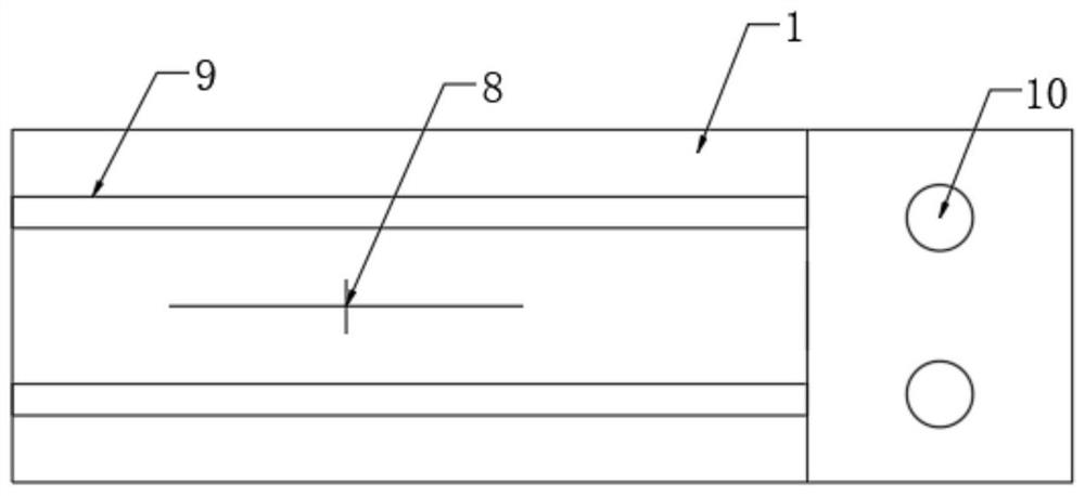
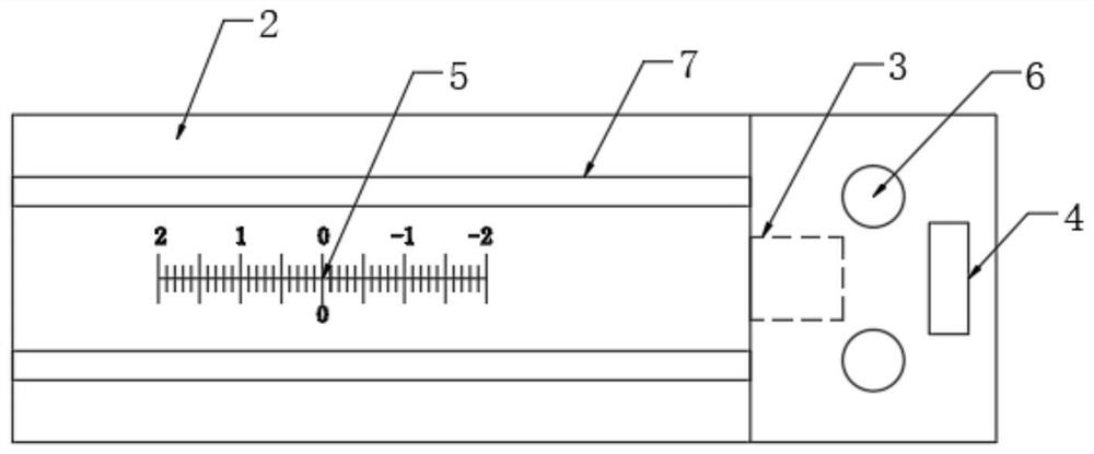
[0033] Embodiment one, with reference to Figure 1-3 , a crack monitoring device for buildings (structures), comprising an upper cover plate 1 and a lower backing plate 2, the bottom side of the upper cover plate 1 is slidably connected with the upper side of the lower backing plate 2 through a sliding assembly, the upper cover plate 1 and the lower backing plate 2 The lower backing plate 2 is provided with a visual scale monitoring component, and the upper end of the lower backing plate 2 is provided with a laser displacement sensor 3 corresponding to the end of the upper cover plate 1 .
[0034] The upper cover plate 1 and the lower backing plate 2 can be respectively fixed on both sides of the crack, and the upper cover plate 1 and the lower backing plate 2 can be combined through the sliding assembly. Relative sliding produces displacement, and the change scale of the crack can be directly read through the visual scale monitoring component. The laser displacement sensor 3 ...
Embodiment 2
[0038] Embodiment two, refer to Figure 1-3 , a device for monitoring cracks in buildings (structures), the structure of this embodiment is roughly the same as that of Embodiment 1, the difference is that:
[0039] It also includes the lower fixing holes 6 and the upper fixing holes 10, the thicker end of the lower backing plate 2 is provided with the lower fixing holes 6, and the thinner end of the upper cover plate 1 is provided with the upper fixing holes 10. The lower backing plate 2 and the upper cover plate 1 can be respectively fixed through the fixing holes 6 at the lower end and the fixing holes 10 at the upper end.
Embodiment 3
[0040] Embodiment three, refer to figure 1 , a building (structure) crack monitoring device, the present embodiment is a further description of embodiment two:
[0041] The sliding assembly includes a sliding convex groove 9 and a sliding groove 7. The bottom of the thinner end of the upper cover plate 1 is provided with a horizontal sliding convex groove 9. There are two sliding convex grooves 9 and they are arranged on the upper cover plate 1. The front and rear sides of the bottom of the thinner end, and the top of the thinner end of the lower backing plate 2 are provided with a sliding groove 7 that is slidably connected with the sliding convex groove 9 . This sliding connection is simple and reliable.
PUM
 Abstract
Description
Claims
Application Information
 - R&D Engineer
- R&D Manager
- IP Professional
- Industry Leading Data Capabilities
- Powerful AI technology
- Patent DNA Extraction
Browse by: Latest US Patents, China's latest patents, Technical Efficacy Thesaurus, Application Domain, Technology Topic, Popular Technical Reports.
© 2024 PatSnap. All rights reserved.Legal|Privacy policy|Modern Slavery Act Transparency Statement|Sitemap|About US| Contact US: help@patsnap.com


