Sludge digestion tank

A digestion tank and sludge technology, applied in biological sludge treatment, chemical instruments and methods, dissolution, etc., can solve problems such as easy accumulation of sludge, poor stirring function of sludge digestion tank, and inability to stir sludge at the bottom. Achieve the effect of improving the stirring effect and reducing the stirring pressure

Pending Publication Date: 2021-11-23
厦门润垣环保科技有限公司
View PDF1 Cites 0 Cited by
  • Summary
  • Abstract
  • Description
  • Claims
  • Application Information

AI Technical Summary

Problems solved by technology

[0003] In the invention patent "A Biological Sludge Anaerobic Digestion System" with the publication number "CN208667263U", it discloses a structure of a sludge digestion tank, the upper side wall of which has a return sludge distribution port, which There is a biogas conveying pipe at the top, which has at least one solid-liquid separator and at least one gas-liquid separator connected to each other (according to the amount of digested sludge, 1-6 solid-liquid separators and 1-3 gas-liquid separators can be set. device), its side wall also has an outlet pipe connected to the gas-liquid separator and a sludge discharge pipe connected to the solid-liquid separator, and a second radio frequency agitator is arranged under the solid-liquid separator; sludge digestion tank 4 The area below the sludge outlet of the return sludge is the sludge digestion reaction zone, and the area between the liquid level of the material in the sludge digestion tank and the top wall of the sludge digestion tank is the biogas buffer zone; the second radio frequency agitator It has 6 to 40 jet nozzles, which can realize 15 to 18 times the mixing volume of the liquid, and the mixing time of the mixed liquid in the sludge digestion tank is 1 to 2 hours; a biogas pressure regulating valve is installed on the biogas delivery pipe, and a biogas pressure regulating valve is installed on the sludge discharge pipe. There is a discharge valve for digested sludge; however, since it is only equipped with a radio frequency stirrer under the solid-liquid separator, the stirring function of the sludge digestion tank is not good, and the sludge at the bottom cannot be stirred, and the dead corner of the tank is easy to accumulate sewage. mud

Method used


Image

  • Sludge digestion tank
  • Sludge digestion tank
  • Sludge digestion tank

Examples


Embodiment Construction

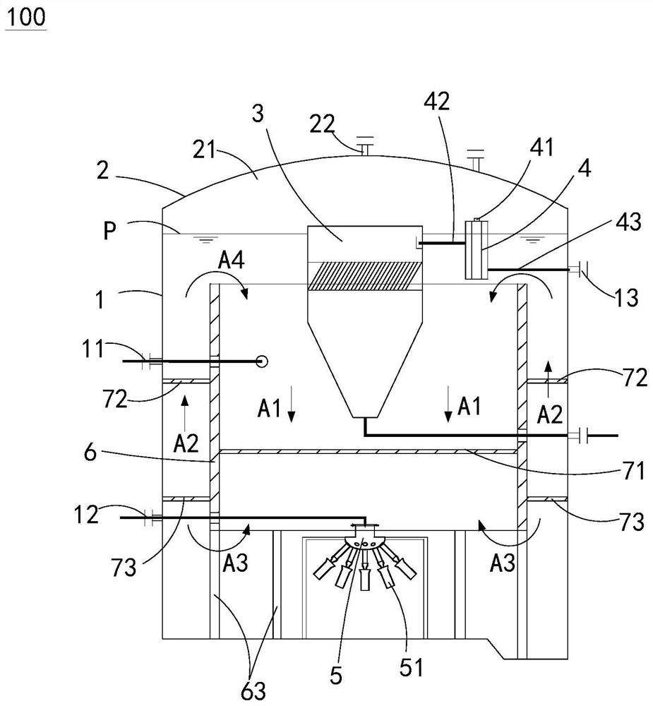
[0023] The embodiment of the present invention provides a sludge digestion tank, which can stir the sludge at the bottom, and can prevent the sludge from accumulating in dead corners of the tank, thereby greatly improving the stirring function.

[0024] The technical solution in the embodiments of the present invention is to solve the above-mentioned problems, and the general idea is as follows: the sludge digestion tank of the present invention sprays water obliquely downwards from the nozzle of the jet agitator, which can impact the dead corners at the bottom of the tank body and avoid pooling at the dead corners. The sludge greatly improves the mixing effect; the tank is equipped with a circulating inner cylinder to separate the space in the tank into multiple areas. After the sludge enters the circulating inner cylinder, it diffuses to the outside of the circulating inner cylinder under the action of the jet agitator, and then It rises from between the circulation inner cyl...


PUM


Abstract

The invention provides a sludge digestion tank. The sludge digestion tank comprises: a tank body, which is provided with a sludge inlet, a water inlet, a water outlet and a sludge discharge outlet; a tank cover, which covers the top of the tank body, defines a gas space above the tank body, and is provided with a biogas conveying opening; a solid-liquid separator, which is suspended at the upper section of the inner space of the tank body, wherein the bottom of the solid-liquid separator is connected with the sludge discharge outlet; a gas-liquid separator, which is suspended at the liquid level of the inner space of the tank body, an exhaust port of the gas-liquid separator communicates with the gas space, a feeding port of the gas-liquid separator is connected with the top of the solid-liquid separator, and a drainage port of the gas-liquid separator is connected with the water outlet; and a jet flow stirrer, which is suspended at the lower section of the inner space of the tank body and comprises a plurality of spray heads, wherein each spray head is obliquely arranged downwards, and jet flow of the spray heads can impact dead angles at the bottom of the tank body. According to the invention, sludge at the bottom can be stirred, sludge accumulation at dead corners of the tank body can be prevented, and a stirring function is greatly improved.

Description

【Technical field】 [0001] The invention relates to a sewage treatment technical field, in particular to a sludge digestion tank. 【Background technique】 [0002] The sludge digestion tank is an important container for the anaerobic sludge digestion reaction in the sewage plant. The operation of the digestion tank not only depends on the biological reaction process, but also its shape and internal stirring are very important. [0003] In the invention patent "A Biological Sludge Anaerobic Digestion System" with the publication number "CN208667263U", it discloses a structure of a sludge digestion tank, the upper side wall of which has a return sludge distribution port, which There is a biogas conveying pipe at the top, which has at least one solid-liquid separator and at least one gas-liquid separator connected to each other (according to the amount of digested sludge, 1-6 solid-liquid separators and 1-3 gas-liquid separators can be set. device), its side wall also has an outle...

Claims


Application Information

Patent Timeline
Patent Type & Authority Applications(China)
IPC IPC(8): C02F11/04B01F13/10
CPCC02F11/04
Inventor 刘超群
Owner 厦门润垣环保科技有限公司
Why Eureka
Try Eureka