
Industrial automatic round log grinding equipment

An industrial round log technology, which is applied in the field of automatic grinding equipment for industrial round logs, can solve the problems of affecting efficiency, staff fatigue, and consuming a lot of time

Pending Publication Date: 2021-11-23
余连秀
View PDF10 Cites 0 Cited by
  • Summary
  • Abstract
  • Description
  • Claims
  • Application Information

AI Technical Summary

Problems solved by technology

[0002] At present, the staff mainly hold the plane to polish the log. During the operation, the staff needs to push and pull the plane repeatedly. For a long time, the staff is tired, and the staff needs to turn the log frequently. While polishing, it will consume a lot of time and seriously affect the efficiency

Method used


Image

  • Industrial automatic round log grinding equipment
  • Industrial automatic round log grinding equipment
  • Industrial automatic round log grinding equipment

Examples


Embodiment 1

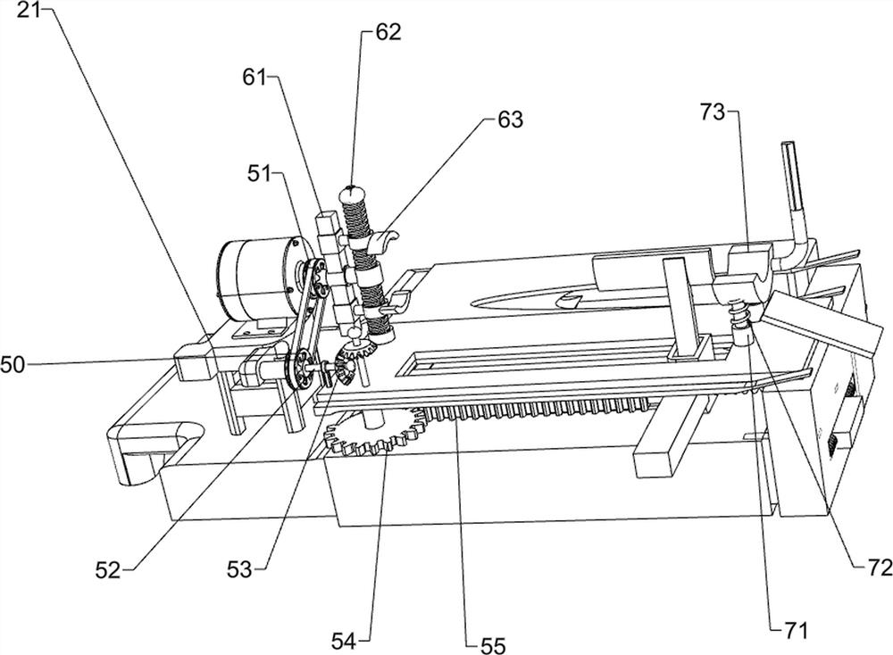
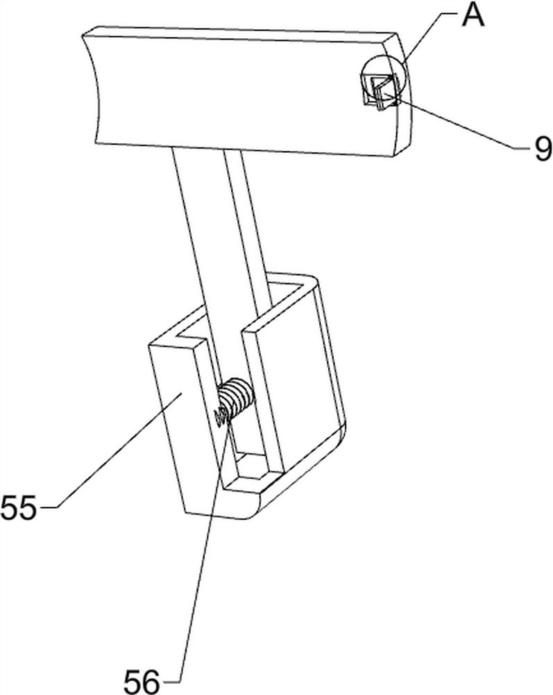
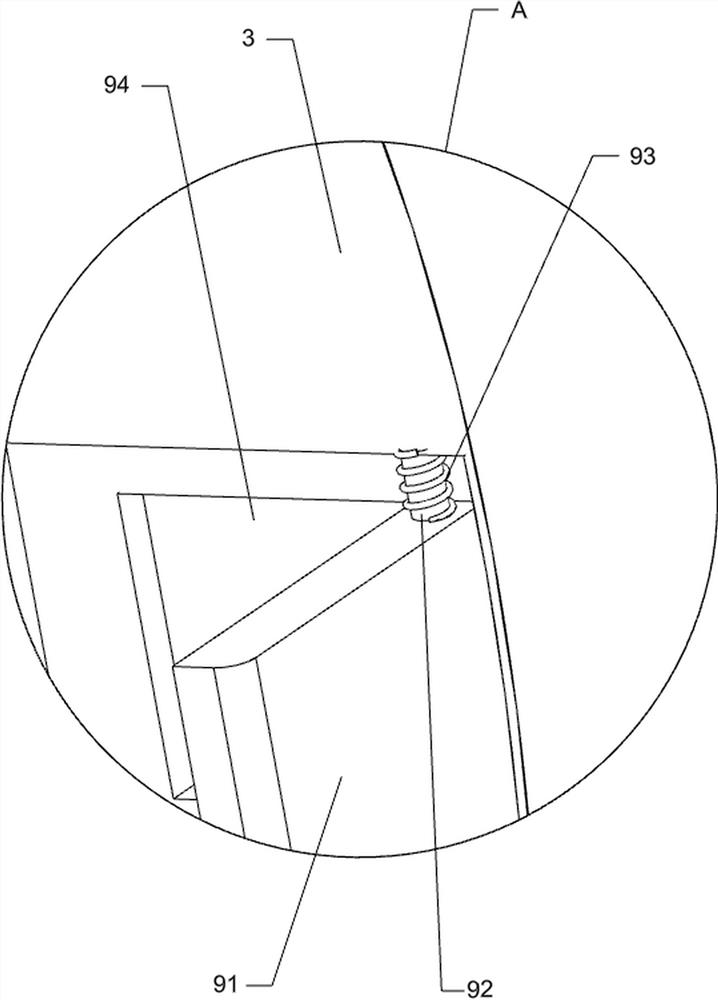
[0024] A kind of automatic grinding equipment for industrial logs, such as Figure 1-3 As shown, it includes a base 1, a mounting base 21, a motor 2, a grinding plate 3, a first spring 4, a moving mechanism 5 and a clamping mechanism 6, a mounting base 21 is provided on the left front side of the top of the base 1, and a mounting base 21 is provided on the mounting base 21. A moving mechanism 5 is connected between the motor 2, the base 1, the mounting seat 21 and the output shaft of the motor 2, the moving mechanism 5 is connected with a grinding plate 3, the first spring 4 is connected between the right side of the grinding plate 3 and the base 1, and the motor 2 The output shaft is connected with a clamping mechanism 6 .

[0025] The moving mechanism 5 includes a transmission wheel 50, a belt 51, a rotating shaft 52, a bevel gear 53, a missing gear 54, a first rack 55 and a second spring 56, and a rotating shaft 52 is rotationally connected between the right front side of t...

Embodiment 2

[0029] On the basis of Example 1, such as figure 1 , figure 2 , Figure 4 , Figure 5 with Image 6 As shown, a support mechanism 7 is also included. The support mechanism 7 includes a telescopic rod 71, a third spring 72 and a support plate 73. Two telescopic rods 71 ​​are arranged on the right side of the top of the base 1, and a support is connected between the tops of the telescopic rods 71. A third spring 72 is arranged between the plate 73 , the front and rear sides of the bottom of the support plate 73 and the bottom of the telescopic rod 71 .

[0030] After people place the log on the support plate 73, due to gravity, the support plate 73 moves downward, so that the telescopic rod 71 and the third spring 72 are compressed, so that the log can be supported and buffered, and the log can be removed. Finally, under the action of the third spring 72, the telescopic rod 71 is driven to stretch and reset, and the supporting plate 73 is driven to move upward and reset.

...


PUM


Abstract

The invention relates to grinding equipment, in particular to industrial automatic round log grinding equipment. The technical problem to be solved is to provide the industrial automatic round log grinding equipment which can enable workers to work easily and save time. According to the technical scheme, the industrial automatic round log grinding equipment comprises a base, a mounting base, a motor, a grinding plate, a first spring, a moving mechanism and a clamping mechanism, the mounting base is arranged on one side of the top of the base, the motor is arranged on the mounting base, the moving mechanism is connected among the base, the mounting base and an output shaft of the motor, the moving mechanism is connected with the grinding plate, the first spring is connected between one side of the grinding plate and the base, and the output shaft of the motor is connected with the clamping mechanism. Through the cooperation of the moving mechanism and the clamping mechanism, a round log can be clamped, and meanwhile, the round log can be ground in the continuous left-right moving process of the round log.

Description

technical field [0001] The invention relates to a grinding device, in particular to an automatic grinding device for industrial logs. Background technique [0002] At present, the staff mainly hold the plane to polish the log. During the operation, the staff needs to push and pull the plane repeatedly. For a long time, the staff is tired, and the staff needs to turn the log frequently. While polishing, it will consume a lot of time and seriously affect efficiency. [0003] In view of the current problems, we design an automatic grinding equipment for industrial round logs that can make it easier for the staff and save time. Contents of the invention [0004] In order to overcome the hand-held planer to polish the log, it will consume a lot of time and seriously affect the efficiency. The technical problem to be solved is: provide an automatic grinding equipment for industrial round logs that can make the staff more relaxed and save time. [0005] The technical solution ...

Claims


Application Information

Patent Timeline
Patent Type & Authority Applications(China)
IPC IPC(8): B24B5/04B24B5/50B24B5/35B24B41/06B24B41/02B24B41/00B24B47/12B24B41/04
CPCB24B5/04B24B5/50B24B5/35B24B5/355B24B41/06B24B41/02B24B41/007B24B47/12B24B41/04
Inventor 余连秀
Owner 余连秀
Learn More