
Full-duplex data communication device

A data communication, full-duplex technology, applied in the field of communication, can solve the problems of the receiver being easily interfered by the transmitter, high power consumption, high power consumption, etc., achieving good interference elimination effect, low power consumption, and power saving Effect

Pending Publication Date: 2021-11-19
TIANJIN 764 COMM AIRMANSHIP
View PDF0 Cites 0 Cited by
  • Summary
  • Abstract
  • Description
  • Claims
  • Application Information

AI Technical Summary

Problems solved by technology

[0002] With the development of science and technology, the demand for communication networks continues to increase. From smart cities, the Internet of Things to various wearable devices, the demand for data transmission rate and transmission quantity is also constantly improving. Full duplex refers to the communication network. At any time, there is two-way signal transmission from A to B and B to A on the line, which can effectively improve the transmission efficiency of data; in full-duplex mode, each end of the communication system is equipped with a transmitter and a receiver, therefore, It can control data to be transmitted in two directions at the same time; this method requires both parties to have a transmitter and a receiver, and at the same time, two data lines are required to transmit data signals; for small wearable devices, full-duplex communication is often There is a problem of high power consumption and high power consumption, which cannot meet people's needs for low power consumption of the Internet of Things. At the same time, there is a problem that the receiver is easily interfered by the transmitter

Method used


Image

  • Full-duplex data communication device
  • Full-duplex data communication device
  • Full-duplex data communication device

Examples


Embodiment Construction

[0022] Embodiments of the present invention are described in detail below, examples of which are shown in the drawings, wherein the same or similar reference numerals designate the same or similar elements or elements having the same or similar functions throughout. The embodiments described below by referring to the figures are exemplary and are intended to explain the present invention and should not be construed as limiting the present invention.

[0023] In the present invention, unless otherwise clearly specified and limited, terms such as "installation", "connection", "connection" and "fixation" should be understood in a broad sense, for example, it can be a fixed connection or a detachable connection , or integrally connected; it may be mechanically connected or electrically connected; it may be directly connected or indirectly connected through an intermediary, and it may be the internal communication of two components. Those of ordinary skill in the art can understand...


PUM


Abstract

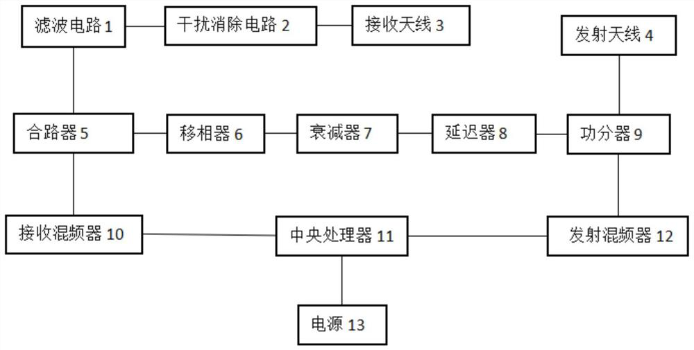
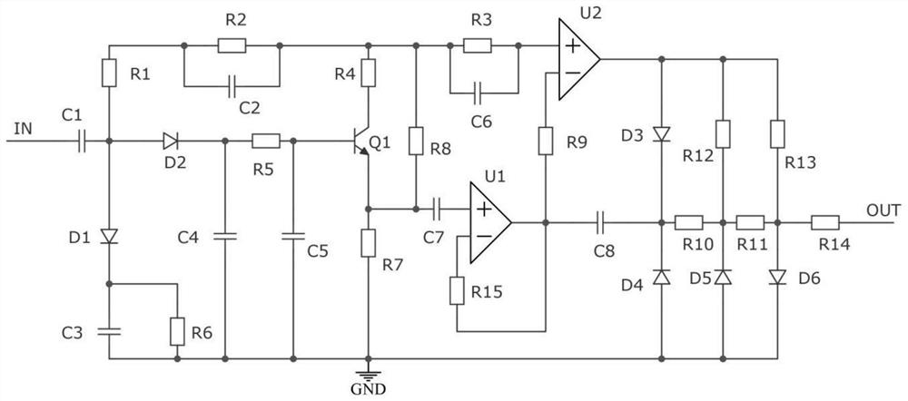
The invention provides a full-duplex data communication device, which comprises a filter circuit, an interference elimination circuit, a receiving antenna, a transmitting antenna, a combiner, a power divider, a receiving frequency mixer, a central processing unit, a transmitting frequency mixer and a power supply. The output end of the receiving antenna is connected with the input end of the interference elimination circuit, the output end of the interference elimination circuit is connected with the input end of the filter circuit, the output end of the filter circuit is connected with the input end of the combiner, the output end of the combiner is connected with the input end of the receiving mixer, and the output end of the receiving mixer is connected with the input end of the central processing unit. The output end of the central processor is connected with the input end of the transmitting mixer, the output end of the transmitting mixer is connected with the input end of the power divider, the output end of the power divider is connected with the input end of the transmitting antenna, and the power supply is connected with the central processor. According to the invention, the interference of the signal transmitted by the transmitting antenna on the signal received by the receiving antenna can be effectively reduced, so that the accuracy of the signal received by the receiving antenna is higher.

Description

technical field [0001] The invention relates to the technical field of communication, in particular to a full-duplex data communication device. Background technique [0002] With the development of science and technology, the demand for communication networks continues to increase. From smart cities, the Internet of Things to various wearable devices, the demand for data transmission rate and transmission quantity is also constantly improving. Full duplex refers to the communication network. At any time, there is two-way signal transmission from A to B and B to A on the line, which can effectively improve the transmission efficiency of data; in full-duplex mode, each end of the communication system is equipped with a transmitter and a receiver, therefore, It can control data to be transmitted in two directions at the same time; this method requires both parties to have a transmitter and a receiver, and at the same time, two data lines are required to transmit data signals; f...

Claims


Application Information

Patent Timeline
IPC IPC(8): H04B1/40H04B1/10H04L5/14
CPCH04B1/40H04B1/10H04L5/14
Inventor 叶萍刘文敬
Owner TIANJIN 764 COMM AIRMANSHIP
Learn More