Electrical connector for circuit boards

A technology for circuit substrates and electrical connectors, which is applied to circuits, connections, and two-component connection devices, etc., can solve problems such as unsmooth assembly, uncertain position of the upper curved portion, and easy elastic deformation.

Pending Publication Date: 2021-11-19
HIROSE ELECTRIC GROUP
View PDF0 Cites 0 Cited by
  • Summary
  • Abstract
  • Description
  • Claims
  • Application Information

AI Technical Summary

Problems solved by technology

[0009] However, since the elastic portion of the terminal is bent and long in the vertical direction, that is, it is long in the assembly direction and is easily elastically deformed, it is conceivable that its posture is unstable during assembly, especially the position of the upper side bending portion in the terminal arrangement direction is not correct. It is confirmed that the top of the upper curved part collides with the protrusion of the movable case before the assembly is completed, and cannot enter between the adjacent protrusions
In addition, if the upper curved portion is slightly plastically deformed due to the collision with the protruding portion, it may not be assembled smoothly even if the assembly is repeated.

Method used


Image

  • Electrical connector for circuit boards
  • Electrical connector for circuit boards
  • Electrical connector for circuit boards

Examples


no. 1 approach >

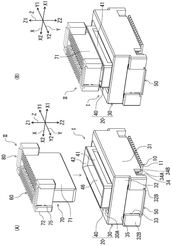
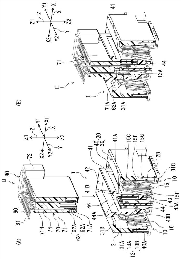
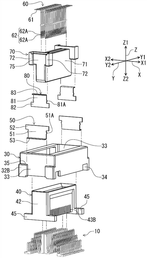
[0030] figure 1 (A), (B), figure 2The plug connector 1 according to this embodiment shown in (A) and (B) is an electrical connector for a circuit board mounted on a mounting surface of a circuit board (not shown). In addition, the receptacle connector II, which is a target connector (target connector) of the plug connector I, is an electrical connector for a circuit board mounted on a mounting surface of another circuit board (not shown). In each of the following figures showing this embodiment, in order to understand the directionality easily, the vertical direction at right angles to the mounting surface of the circuit board is set as the connector height direction Z, and the terminal arrangement direction in the connector is set as Let it be Y, and let X be the connector width direction which is the direction perpendicular|vertical to two directions of the connector height direction Z and the terminal arrangement direction Y. The plug connector I and the receptacle conne...

no. 2 approach >

[0077] Figure 8 The second embodiment shown is different from the first embodiment in which the plug terminal is manufactured by punching a metal plate member in the thickness direction, and is characterized in that the plug terminal 110 is manufactured by bending a metal strip member in the thickness direction. The bottom surface side protrusion 143E formed on the bottom surface of the bottom wall 143 of the entrance wall portion 140A of the movable housing 140 protrudes downward from the plug terminal 110, and the rest is the same as that of the first embodiment, and corresponds to the first embodiment. The reference numerals added with "100" to the reference numerals in the first embodiment are assigned to the parts of , and redundant descriptions are omitted.

[0078] Such as Figure 8 As shown, the plug terminal 110 is a so-called bent terminal formed by bending a metal strip member in the thickness direction, and has a substantially M-shaped elastic portion 115 between...


PUM


Abstract

The invention provides an electrical connector for circuit boards that allows for easy and reliable incorporation of terminals with resilient portions and makes it possible for contact between terminals to be prevented even if the resilient portions undergo considerable resilient deformation.A movable housing has an entry wall portion that enters the interior space of the stationary housing and is located in a spaced-apart relationship with said stationary housing; terminal holding grooves, which extend in the direction of connection and are used for accommodating portions of the resilient portions, are formed and arranged in the terminal array direction on one wall surface of said entry wall portion; movable-side terminal holding portions, which secure the movable-side retained portions of the terminals in place, are formed on the back side, that is, the opposite side relative to one wall surface; and, furthermore, between adjacent terminal holding grooves, the movable housing has projections that extend in the direction of connection from the distal end portion facing the circuit board side of the entry wall portion; and, when the terminals are attached in the direction of connection from the circuit board side, gaps are formed between the projections and the resilient portions of the terminals located within the terminal holding grooves in the terminal array direction.

Description

technical field [0001] The present invention relates to an electrical connector for a circuit board mounted on a circuit board. Background technique [0002] For example, Patent Document 1 discloses such an electrical connector for a circuit board. The electrical connector for a circuit board of Patent Document 1 is a so-called floating connector, and has a fixed case mounted on the circuit board, and a movable case that is fitted and connected to a mating connector and is movable relative to the fixed case, A plurality of terminals ("receptacle contacts" in Patent Document 1) are mounted side by side in a state straddling the fixed case and the movable case. An elastic part ("displacement part" in Patent Document 1) having a shape bent at the middle part in the longitudinal direction of the terminal is formed on the terminal. Due to the elastic deformation of the elastic part, the movable housing is relatively fixed The housing is removable. [0003] The above-mentioned ...

Claims


Application Information

Patent Timeline
Patent Type & Authority Applications(China)
IPC IPC(8): H01R12/71H01R13/502H01R13/40H01R13/11H01R13/02
CPCH01R12/716H01R13/502H01R13/40H01R13/11H01R13/02H01R12/73H01R12/91H01R24/60H01R13/6315H01R12/737
Inventor 土井健太郎
Owner HIROSE ELECTRIC GROUP
Why Eureka
Try Eureka