Thread guide bar improved arrangement for circular knitting machines

The technology of a yarn guide rod and a circular knitting machine is applied in the directions of weft knitting, textiles, papermaking, knitting, etc., and can solve the problems of inconvenient assembly of the yarn support rod seat, difficulty and difficulty in connecting and installing the linkage mechanism, etc.

Inactive Publication Date: 2005-11-02
陈仁惠 +1
View PDF0 Cites 11 Cited by
  • Summary
  • Abstract
  • Description
  • Claims
  • Application Information

AI Technical Summary

Problems solved by technology

[0003] When the above-mentioned device is combined, it is necessary to pass the bent part of the yarn support rod through the seat shell first, and then assemble and connect the peripheral components of the yarn support rod in the seat shell, such as connectors, compression springs, etc., and then assemble the cover The outer end of the bending part of the yarn support rod is assembled and positioned with the shaft seat and the cover body, and the positioning of the adjustment block needs to be taken into account, so its assembly is quite cumbersome and difficult. It is very difficult to connect and install the linkage mechanism by piercing the bending part of the rod into the seat shell, and it needs to be improved.
[0004] In view of the disadvantages of the above-mentioned rather inconvenient assembly of the yarn support rod seat and the unsatisfactory structural design, the inventor of this case, based on years of experience in research and development in this industry, provides a circular knitting machine with more convenience for assembly. The improved device of the yarn guide rod of the machine serves the industry, and after a long period of research and development, the present invention is produced

Method used


Image

  • Thread guide bar improved arrangement for circular knitting machines
  • Thread guide bar improved arrangement for circular knitting machines
  • Thread guide bar improved arrangement for circular knitting machines

Examples


Embodiment Construction

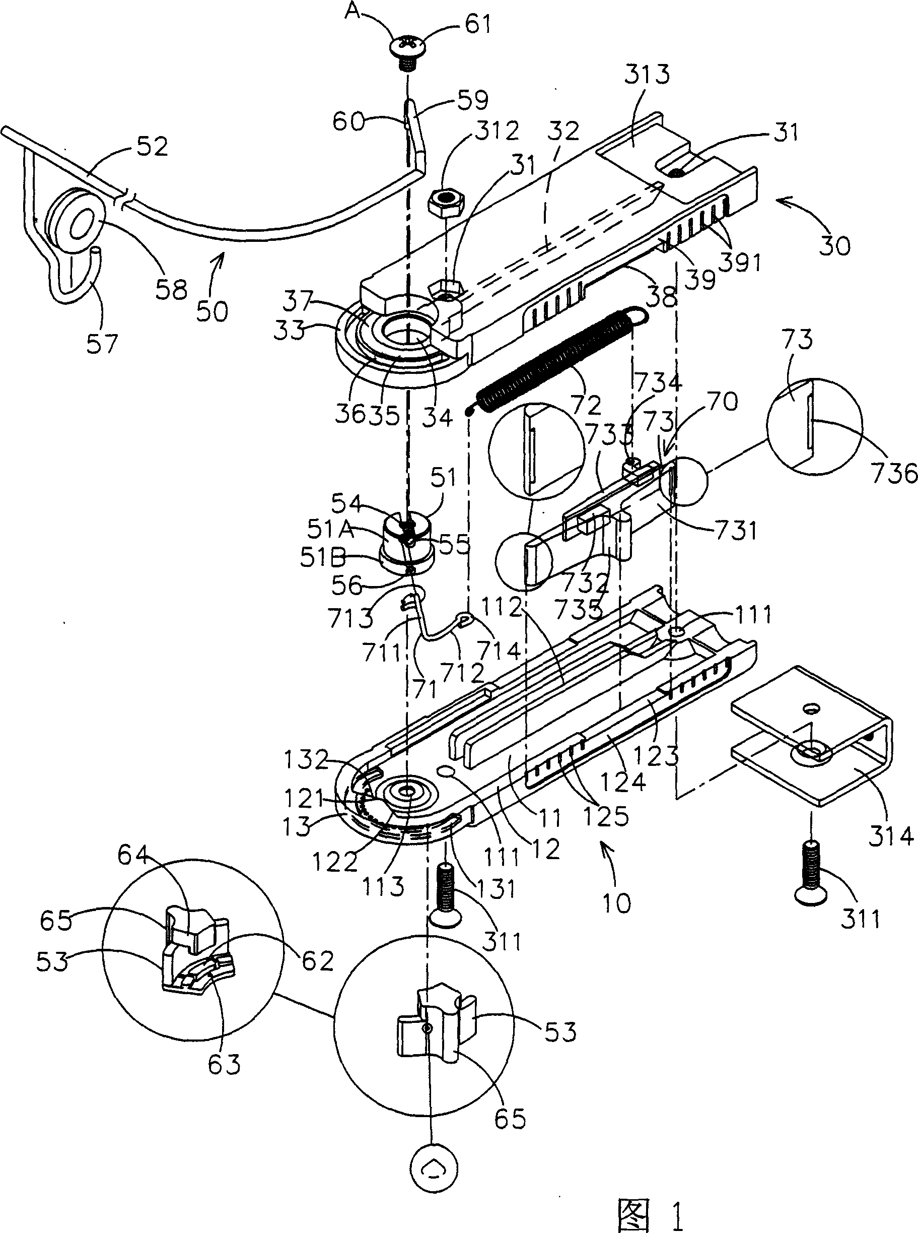
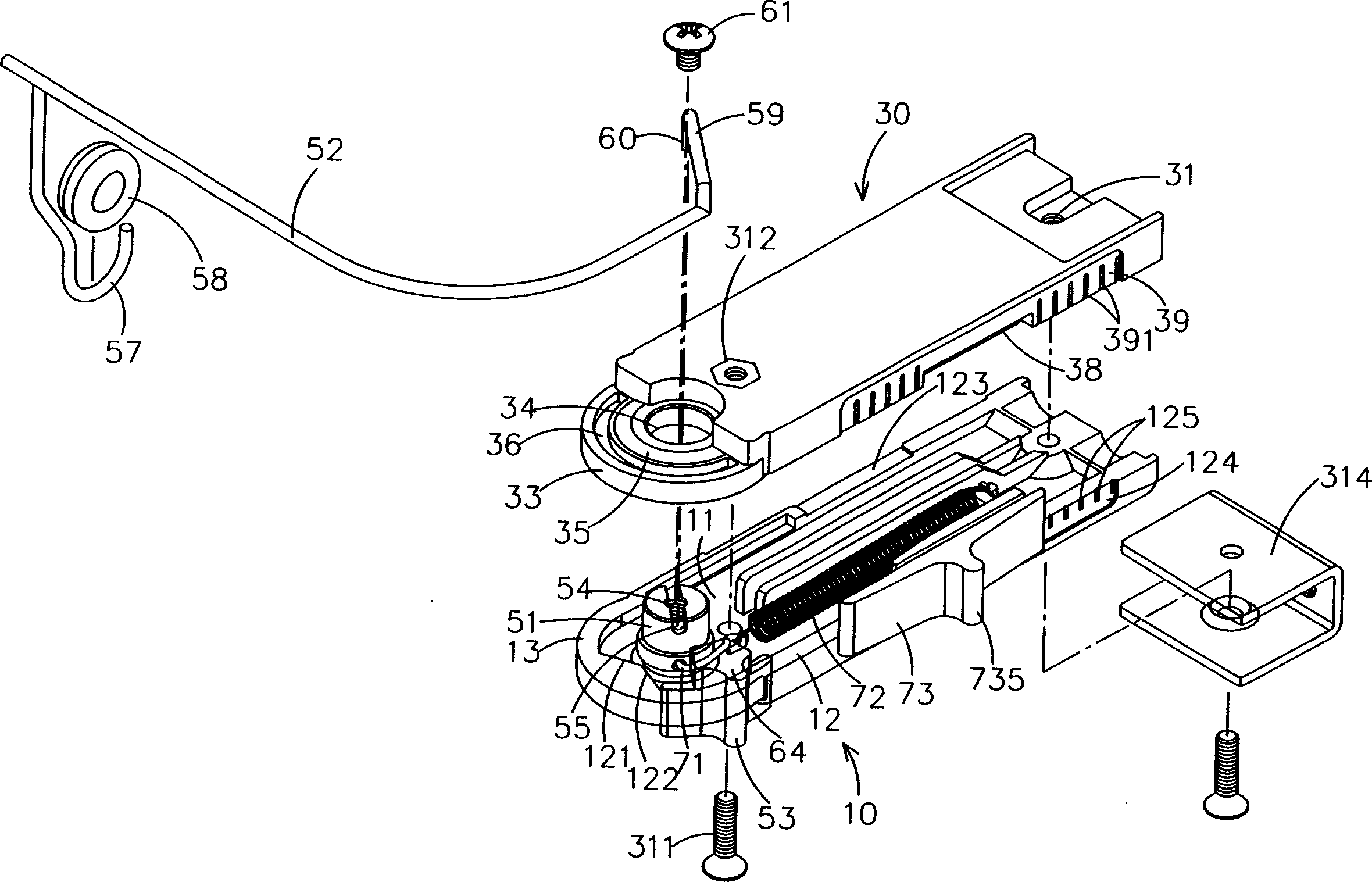
[0023] Please refer to Figures 1 to 3, the improved device of the yarn guide rod device of the circular knitting machine of the present invention includes a base 10, a cover body 30, a swing mechanism 50 and a tension mechanism 70, the base 10 includes a bottom surface 11 and a convex peripheral edge 12, And the front end of the base 10 is an arc joint 13, the bottom surface 11 is provided with a positioning hole 111 and a groove rib 112, and the front end of the bottom surface 11 is provided with a convex mandrel positioning portion 113, the positioning portion 113 can be a flange or a shaft hole. The convex peripheral edge 12 is provided with a mountain-shaped part 121 at the arc joint 13. The mountain-shaped part 121 has an inclined contact surface 122. The convex peripheral edge 12 is on both sides of the bottom surface 11. The recess 123 on the top surface and the groove 124 on the side are symmetrically provided, and the groove 124 is provided with a plurality of position...


PUM


Abstract

The invention provides an improved structure of thread guide bar block of knitting machine, including a base, a cover, swing mechanism and tension mechanism. The base has a spindle positioning part; the cover with a through axle hole is connected to the base and cover it; the swing mechanism includes at least a spindle and a thread guide bar, while the spindle, with a screw hole and a locating slot transversely connecting this screw hole, is mounted between the spindle positioning part of base and the axle hole of cover; said thread guide bar is embedded in the locating slot of this spindle and locked with the screw hole by a bolt to depend and be located on the thread guide bar; said tension mechanism includes a connecter, extension spring, and tension adjusting knob, wherein, one end of the connecter links said spindle, and another one links said extension spring; said tension adjusting knob embedded into the side of base and cover connects extension spring; by this structure, quick and easy installment of this thread guide bar is reached, and the economic benefit is improved.

Description

technical field [0001] The present invention relates to a yarn guide rod device, especially a yarn guide rod for a circular knitting machine which has reliable yarn guide action, quick and convenient assembly of the yarn guide rod and the whole yarn guide rod device Device improvements. Background technique [0002] Press, when the general circular knitting machine (circular knitting machine) performs color changing operation, it mainly uses a yarn guide rod to generate deflection and displacement action to achieve it. The relevant yarn guide rod seat structure is as shown in the announcement No. Color-changing yarn feeder's improved device for the support rod seat" patent case, which includes a seat shell, tension spring, cover body and support rod and other components, wherein the support rod is a long rod body with a yarn eye at one end hole, and the other end has a bent part, the inner end of the bent part of the yarn support rod is pivotally arranged in the predetermin...

Claims


Application Information

Patent Timeline
Patent Type & Authority Applications(China)
IPC IPC(8): D04B15/58
Inventor 陈仁惠陈佩莹
Owner 陈仁惠
Why Eureka
Try Eureka