
Water rocket pressure-operated interstage locking-separating device

A separation device and a water rocket technology, applied in the field of power aviation, can solve the problems of inability to fully utilize mechanical energy, unadjustable trigger points, and reduce the performance of water rockets, achieving high action triggering accuracy, improving overall ceiling, and wide working pressure range Effect

Active Publication Date: 2021-11-16
NAT UNIV OF DEFENSE TECH
View PDF9 Cites 1 Cited by
  • Summary
  • Abstract
  • Description
  • Claims
  • Application Information

AI Technical Summary

Problems solved by technology

[0015] ①The working pressure range is narrow, and the trigger point of separation between stages cannot be adjusted
Because it realizes inter-stage locking and separation based on the deformation of the hose, when the pressure difference between the internal pressure of the water rocket of the lower stage and the pressure of the water rocket of the upper stage reaches 2bar, the separation of the rocket body will be triggered, which limits the maximum storage capacity of the upper water rocket. Pressure, on the other hand, also makes the interstage separation occur prematurely, and the mechanical energy stored in the lower stage water rocket cannot be fully utilized
[0016] ②The maximum withstand pressure is low
Due to the existence of the above-mentioned pressure difference design, the maximum withstand pressure that the interstage lock-separator can work is lower than the maximum pressure that the rocket body itself can withstand, which reduces the performance of the water rocket

Method used


Image

  • Water rocket pressure-operated interstage locking-separating device
  • Water rocket pressure-operated interstage locking-separating device
  • Water rocket pressure-operated interstage locking-separating device

Examples


Embodiment Construction

[0036] In order to make the purpose, technical solution and advantages of the present invention clearer, the technical solution of the present invention will be clearly and completely described below in conjunction with specific embodiments of the present invention and corresponding drawings. Apparently, the described embodiments are only some of the embodiments of the present invention, but not all of them. Based on the embodiments of the present invention, all other embodiments obtained by persons of ordinary skill in the art without making creative efforts fall within the protection scope of the present invention.

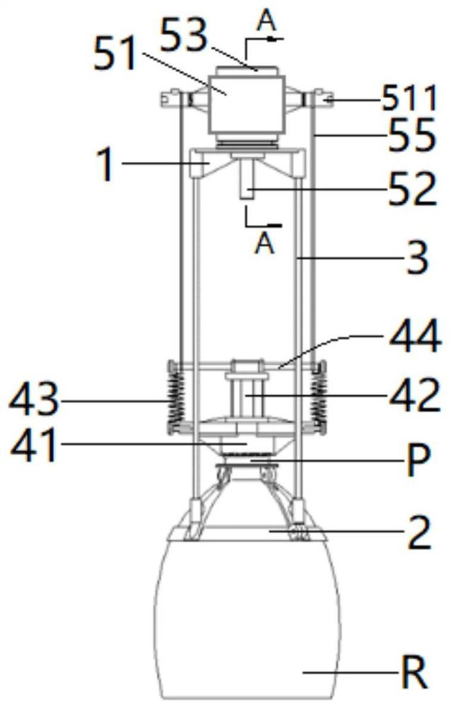
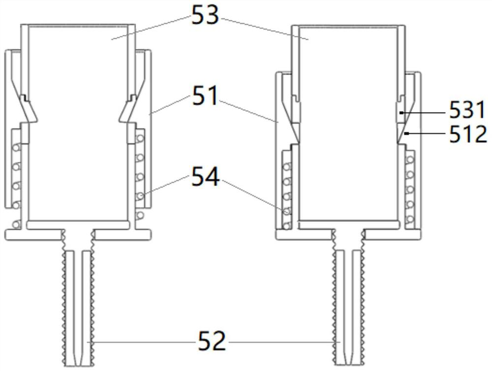
[0037] Such as figure 1 , figure 2 , Figure 3a and Figure 3b As shown, the water rocket pressure type interstage locking-separation device of the present invention includes: an upper base 1, a lower fixed anchor base 2, a plurality of support columns 3 connected between the upper base 1 and the lower fixed anchor base 2 , Piston-spring assembly 4, lock-se...


PUM


Abstract

The invention discloses a water rocket pressure-operated interstage locking-separating device, which comprises an upper base, a lower fixing anchor seat, a supporting stand column, a piston-spring assembly and a locking-separating device. The lower fixing anchor seat is sleeved and fixed at the upper end of the rocket body of a lower-stage water rocket; the piston-spring assembly comprises a cylinder barrel, a piston, tension springs and a tension spring hanging rod, the cylinder barrel is fixedly arranged on the periphery of an upper end opening of a rocket body of the lower-stage water rocket in a sleeving mode, the piston is communicated with the interior of the lower-stage water rocket and keeps consistent pressure, the tension spring hanging rod is fixed to the piston, one end of each tension spring is hung at the two side ends of the tension spring hanging rod respectively, and the other end of each tension spring is fixed on the cylinder barrel; and the locking-separating device is fixed to the upper base, and an upper-stage water rocket body is connected to the locking-separating device. According to the device, locking and separating of all stages of the water rocket are achieved, the overall lift limit of the water rocket is improved, the functions of the water rocket and the load capable of being carried by the water rocket are expanded, the working pressure range is wide, and the pressure adjusting freedom degree is high.

Description

technical field [0001] The invention belongs to the technical field of power aviation, and in particular relates to a water rocket pressure-operated interstage locking-separating device. Background technique [0002] The water rocket assisted glider is a common combined power aviation model. This model is mainly composed of three parts: a water rocket, a fixed-wing glider, and a connection-separation device between the two. One of the main competition items of the Air Vehicle Design Challenge. [0003] The working process of the water rocket-assisted glider is similar to that of the launch vehicle: in the boosting ascent phase, the water rocket carries the glider into the sky and separates the glider at the highest point of the water rocket’s flight trajectory; in the descent phase, the water rocket separates the glider Afterwards, the parachute is opened to achieve a soft landing, and the glider performs flight tasks under the control of the pilot or algorithm, such as gl...

Claims


Application Information

Patent Timeline
IPC IPC(8): G09B25/02
CPCG09B25/02
Inventor 赵勇梁昊鹏张海栋陈德峻谢士娇
Owner NAT UNIV OF DEFENSE TECH
Learn More