
A Spectrum Prediction Method of Wall Surface Fluctuation Pressure in Laminar Flow Area of ​​Underwater Vehicle Surface

An underwater vehicle, pulsating pressure technology, applied in instruments, design optimization/simulation, calculation, etc., can solve the problems of difficult to guarantee accuracy, lack of theoretical basis, difficult to predict results, etc., and achieve small calculation amount and reliable calculation results. Effect

Active Publication Date: 2022-05-20
TIANJIN UNIV
View PDF3 Cites 0 Cited by
  • Summary
  • Abstract
  • Description
  • Claims
  • Application Information

AI Technical Summary

Problems solved by technology

This method lacks a theoretical basis, and requires experience to set parameter values ​​for prediction, and the prediction accuracy for unknown working conditions is low
Moreover, for the high Reynolds number flow of large underwater vehicles, there is a lack of corresponding experimental data and numerical simulation results, and it can only be promoted based on the results of the scale model and low Reynolds number based on experience, and the accuracy is even more difficult to guarantee.
Therefore, it seems that this method is difficult to give accurate prediction results in practical engineering problems

Method used


Image

  • A Spectrum Prediction Method of Wall Surface Fluctuation Pressure in Laminar Flow Area of ​​Underwater Vehicle Surface
  • A Spectrum Prediction Method of Wall Surface Fluctuation Pressure in Laminar Flow Area of ​​Underwater Vehicle Surface
  • A Spectrum Prediction Method of Wall Surface Fluctuation Pressure in Laminar Flow Area of ​​Underwater Vehicle Surface

Examples


Embodiment Construction

[0042] The present invention will be described in detail below in conjunction with specific embodiments and accompanying drawings. In the following description, for purposes of explanation and not limitation, specific details are set forth in order to provide a thorough understanding of the invention. It will be apparent, however, to one skilled in the art that the present invention may be practiced in other embodiments that depart from these specific details.

[0043]It should be noted here that, in order to avoid obscuring the present invention due to unnecessary details, only the device structure and / or processing steps closely related to the solution according to the present invention are shown in the drawings, and the steps related to the present invention are omitted. Invent other details that don't really matter.

[0044] An embodiment of the present invention provides a method for predicting the wall surface fluctuating pressure spectrum in the laminar flow region on ...


PUM


Abstract

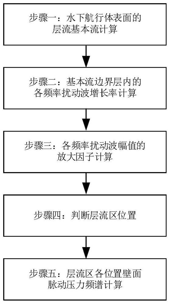
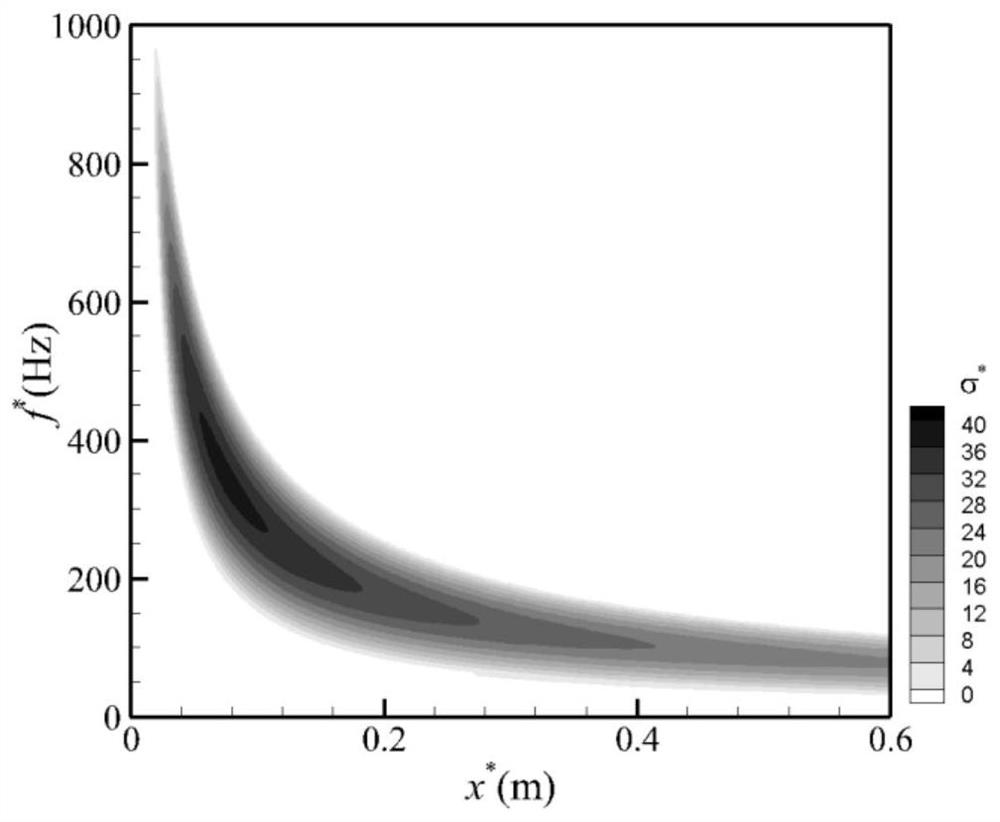
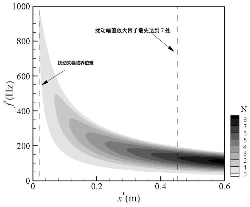
The invention relates to a method for predicting the wall surface pulsation pressure spectrum in the laminar flow area on the surface of an underwater vehicle, comprising the following steps: determining the basic flow of the laminar flow on the surface of the underwater vehicle to be analyzed; obtaining the boundary of the basic flow of the laminar flow on the surface of the underwater vehicle The growth rate of the disturbance wave amplitude of each frequency in the layer along the flow direction; the obtained disturbance wave amplitude growth rate of different frequencies is integrated along the flow direction to obtain the amplification factor of the disturbance wave amplitude of each frequency; the obtained amplitude amplification factor , judge the location of the laminar flow region by the transition criterion, that is, from the front edge of the boundary layer to the downstream, the maximum amplitude amplification factor of each flow position first reaches the value given by the transition criterion, which is the transition start position, and the transition Before the initial position of the transition is the laminar flow area; the wall pulsation pressure spectrum in the laminar flow area is the relative multiple spectrum of the pressure disturbance amplitude at different frequencies. The magnification of the value is calculated.

Description

Technical field: [0001] The invention relates to the technical field of hydrodynamic research, in particular to a method for predicting a frequency spectrum of pressure fluctuations on a wall in a laminar flow region on the surface of an underwater vehicle. Background technique: [0002] Acoustic waves are a form of energy that can travel long distances in water media, and wall pulsating pressure is an important source of hydrodynamic noise for underwater vehicles. Very loud noise can interfere with the detection and communication of underwater vehicles. In order to improve the detection and communication capabilities of underwater vehicles, it is one of the feasible measures to improve the noise source. To propose improvements, it is necessary to know how the noise source behaves. Therefore, the wall pulsating pressure of underwater vehicles has always been an important issue of scientific and engineering concern. [0003] For the prediction of the pressure spectrum of t...

Claims


Application Information

Patent Timeline
Patent Type & Authority Patents(China)
IPC IPC(8): G06F30/28G06F113/08G06F119/14
CPCG06F30/28G06F2113/08G06F2119/14Y02T90/00
Inventor 张永明刘竟成
Owner TIANJIN UNIV
Learn More