
LCD with contrast improving structure

A technology of LCD display and contrast, which is applied in instruments, nonlinear optics, optics, etc. It can solve problems such as light leakage, polarizer polarization degree cannot reach theoretical 100%, limit LCD dynamic range, etc., and achieve ultra-high contrast Effect

Pending Publication Date: 2021-11-16
HUIZHOU TCL CLOUD INTERNET CORP TECH CO LTD
View PDF5 Cites 1 Cited by
  • Summary
  • Abstract
  • Description
  • Claims
  • Application Information

AI Technical Summary

Problems solved by technology

Such a contrast greatly limits the dynamic range of the LCD, making the effect of the LCD display worse than that of the OLED display when performing HDR playback.
[0003] In the traditional scheme, the traditional LCD display technology consists of white backlight plus TFT-cell, and polarizers are pasted on both sides of the cell. However, because the transmittance of the polarizer and the degree of polarization are mutually exclusive, the degree of polarization is generally between 90-99%, that is, the total A small amount of light will leak out, causing the dark part of the LCD to not be black enough so that the LCD contrast can only be maintained at the level of 800-2000
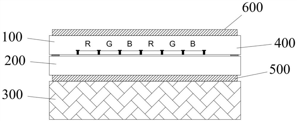
[0004] figure 1 For the traditional solution, 100 is CF (color filter), 200 is array (TFT array, active switch matrix; TFT-thin film field effect tube), 300 is backlight, 400 is BM (blackmatrix-black matrix), 500 is down Polarizer, 600 is the upper polarizer; in the traditional scheme, the color, light and dark changes are realized by switching the red, green and blue sub-pixels, but the degree of polarization of the polarizer cannot reach the theoretical 100% and the films in the LCD box The complex relationship of transmission, reflection, and refraction prevents the pixels from being completely closed, that is, the light from the backlight always leaks through the LCD to reach the human eye. Therefore, the contrast ratio of LCD cannot be tens of millions like OLED

Method used


Image

  • LCD with contrast improving structure
  • LCD with contrast improving structure

Examples


Embodiment Construction

[0021] In order to enable those skilled in the art to better understand the solutions of the present invention, the following will clearly and completely describe the technical solutions in the embodiments of the present invention in conjunction with the drawings in the embodiments of the present invention. Obviously, the described embodiments are only It is an embodiment of a part of the present invention, but not all embodiments. Based on the embodiments of the present invention, all other embodiments obtained by persons of ordinary skill in the art without making creative efforts shall fall within the protection scope of the present invention. The embodiments described by referring to the figures are exemplary only for explaining the present invention and should not be construed as limiting the present invention. Also, detailed descriptions of known arts will be omitted if they are unnecessary to illustrate the features of the present invention.

[0022] It should be noted...


PUM


Abstract

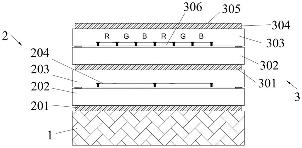
The invention relates to the field of display devices, in particular to an LCD with a contrast improving structure. The LCD comprises a backlight layer, a backlight control layer and a light display layer, wherein the backlight layer, the backlight control layer and the light display layer are connected in sequence, the backlight layer is used for emitting a light source, the backlight control layer filters a light source emitted by the backlight layer, a light display surface is arranged on the light display layer, and the light display surface displays the visible light filtered by the backlight control layer. According to the invention, the backlight control layer is arranged between the backlight layer and the light display layer, and pixel-level filtering control is carried out on light transmission by arranging the backlight control layer, so that light of the black area part of the light display layer is blocked to extremely low brightness, and light reaching the light display layer cannot penetrate through a display surface so as to achieve the ultra-high contrast of the display surface of the light display layer.

Description

technical field [0001] The invention relates to the field of displays, in particular to an LCD display with a contrast-enhancing structure. Background technique [0002] With the evolution of technology, the display industry has begun to gradually transition from LCD (Liquid Crystal Display) to OLED (Organic Diode Display). Compared with the bright and high dynamics of OLED, LCD has an obvious disadvantage in dynamic range, that is, LCD contrast is insufficient. Compared with the contrast ratio of tens of millions of OLEDs, conventional LCDs only have a contrast ratio of 1000-3000. Such a contrast greatly limits the dynamic range of the LCD, so that the LCD is obviously less effective than the OLED display when performing HDR playback. [0003] In the traditional scheme, the traditional LCD display technology consists of white backlight plus TFT-cell, and polarizers are pasted on both sides of the cell. However, because the transmittance of the polarizer and the degree of p...

Claims


Application Information

Patent Timeline
Patent Type & Authority Applications(China)
IPC IPC(8): G02F1/13357G02F1/1335
CPCG02F1/133606G02F1/1336G02F1/133528G02F1/133514
Inventor 罗光跃罗杰赵允国
Owner HUIZHOU TCL CLOUD INTERNET CORP TECH CO LTD
Learn More