
Automatic focusing method for photo-thermal reflection microscopic thermal imaging and control device

A micro-thermal imaging and auto-focusing technology, applied in the direction of microscopes, optics, optical components, etc., can solve problems such as insufficient consistency, inaccurate measurement results, and affecting the focus stability of multi-frame acquisition images, so as to improve accuracy, Improve focus efficiency and ensure focus stability

Pending Publication Date: 2021-11-16
THE 13TH RES INST OF CHINA ELECTRONICS TECH GRP CORP
View PDF0 Cites 0 Cited by
  • Summary
  • Abstract
  • Description
  • Claims
  • Application Information

AI Technical Summary

Problems solved by technology

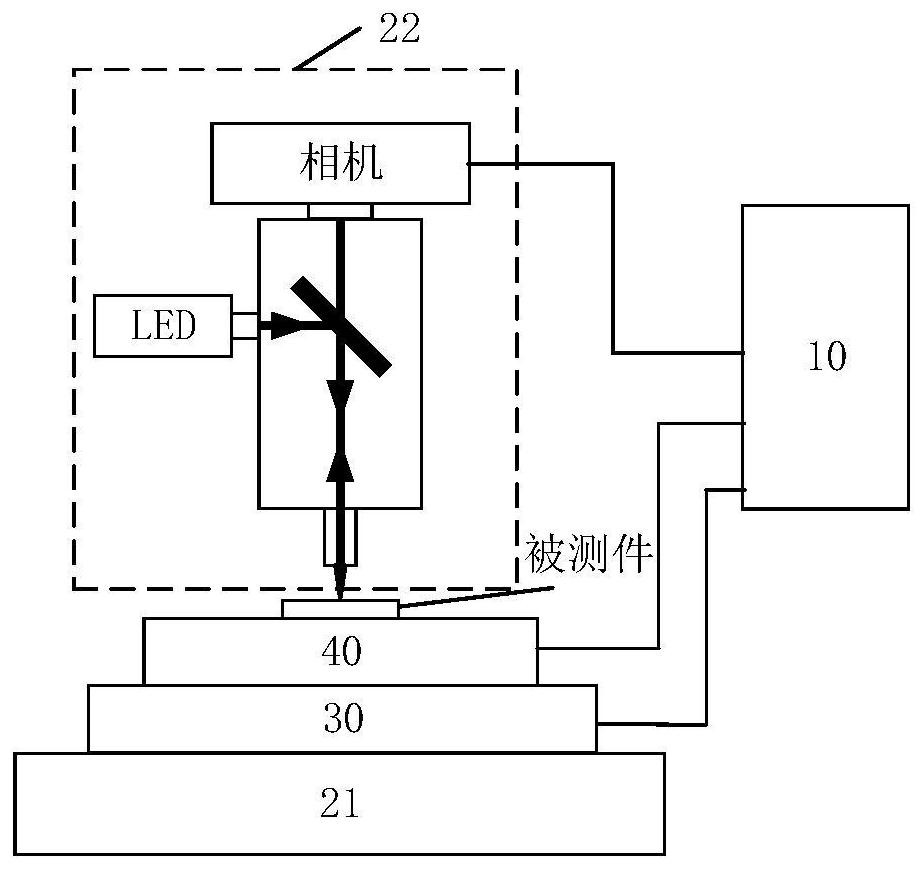
[0005] The embodiment of the present invention provides an automatic focusing method and control device for photothermal reflection microscopic thermal imaging, to solve the problem that the existing manual focusing method is not consistent enough, which affects the focusing stability of multi-frame acquisition images, resulting in measurement results inaccurate question

Method used


Image

  • Automatic focusing method for photo-thermal reflection microscopic thermal imaging and control device
  • Automatic focusing method for photo-thermal reflection microscopic thermal imaging and control device
  • Automatic focusing method for photo-thermal reflection microscopic thermal imaging and control device

Examples


Embodiment Construction

[0047] In the following description, for the purpose of illustration rather than limitation, specific details such as specific system structures and technologies are set forth in order to provide a thorough understanding of the embodiments of the present invention. However, it will be apparent to those skilled in the art that the present invention may be practiced in other embodiments without these specific details. In other instances, detailed descriptions of well-known systems, devices, circuits, and methods are omitted so as not to obscure the description of the present invention with unnecessary detail.

[0048] In order to make the objectives, technical solutions and advantages of the present invention clearer, the following descriptions will be given through specific embodiments in conjunction with the accompanying drawings.

[0049] In the existing reports, the change of reflectance with temperature can be considered to be linear, so it can be characterized by a rate of...


PUM


Abstract

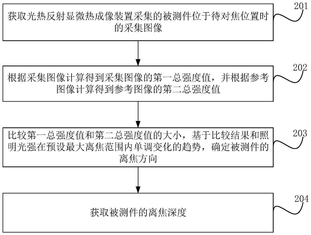
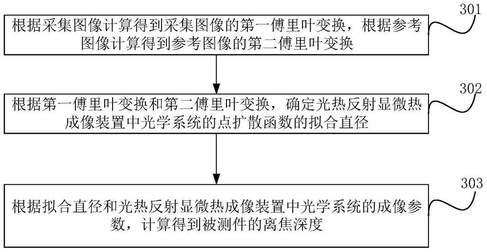
The invention provides an automatic focusing method for photo-thermal reflection microscopic thermal imaging and a control device. The method comprises the following steps: acquiring an acquired image when a measured piece is located at a to-be-focused position and a reference image when the measured piece is located at a focusing position, wherein the acquired image is acquired by a photo-thermal reflection microscopic thermal imaging device of which the illumination light intensity monotonically changes within a preset maximum defocusing range; calculating to obtain a first total intensity value according to the collected image, and calculating to obtain a second total intensity value according to the reference image; comparing the first total intensity value with the second total intensity value, and determining the defocus direction of the tested piece based on the comparison result and the monotonous change trend of the illumination light intensity in the preset maximum defocus range; obtaining the defocus depth of the measured piece, wherein the out-of-focus direction and the out-of-focus depth are used for focusing the measured piece. According to the invention, while the focusing efficiency is improved, the problem of insufficient consistency of manual focusing is avoided, the focusing stability of multiple frames of collected images is ensured, and the accuracy of a measurement result during temperature measurement based on photo-thermal reflection is improved.

Description

technical field [0001] The invention relates to the technical field of microscopic thermal imaging, in particular to an automatic focusing method and a control device for photothermal reflection microscopic thermal imaging. Background technique [0002] Photothermal reflection temperature measurement technology is a non-contact temperature measurement technology, which is based on the phenomenon of photothermal reflection. [0003] When measuring temperature based on photothermal reflection, in order to achieve microscopic thermal imaging with high spatial resolution, a photothermal reflection microscope imaging device is usually constructed based on a high-performance optical microscope. The probe light is provided by the illumination optical path system of the optical microscope, the microscopic imaging is recorded by a high-performance camera, and the output camera reading is used as the measurement value. [0004] However, in the process of temperature measurement, in o...

Claims


Application Information

Patent Timeline
IPC IPC(8): G02B21/24G06F17/14
CPCG02B21/244G06F17/141
Inventor 刘岩乔玉娥邹学峰丁立强吴爱华赵英伟李锁印
Owner THE 13TH RES INST OF CHINA ELECTRONICS TECH GRP CORP
Learn More