
Laser reflector seat capable of eliminating resonance effect generated by machine motion

A mirror seat and resonance effect technology, applied in optics, instruments, optical components, etc., can solve problems such as optical path offset, optical path focus position, focus point offset, ghosting, vibration, etc., to eliminate optical path swing offset, ensure The effect of focus stabilization

Pending Publication Date: 2021-07-27
世一激光设备(绍兴)有限公司
View PDF4 Cites 1 Cited by
  • Summary
  • Abstract
  • Description
  • Claims
  • Application Information

AI Technical Summary

Problems solved by technology

However, due to the movement of the machine and the long-distance optical path transmission, the optical path shifts and shakes, which will cause focus point shift ghosting at the focusing position of the optical path

Method used


Image

  • Laser reflector seat capable of eliminating resonance effect generated by machine motion
  • Laser reflector seat capable of eliminating resonance effect generated by machine motion
  • Laser reflector seat capable of eliminating resonance effect generated by machine motion

Examples


Embodiment Construction

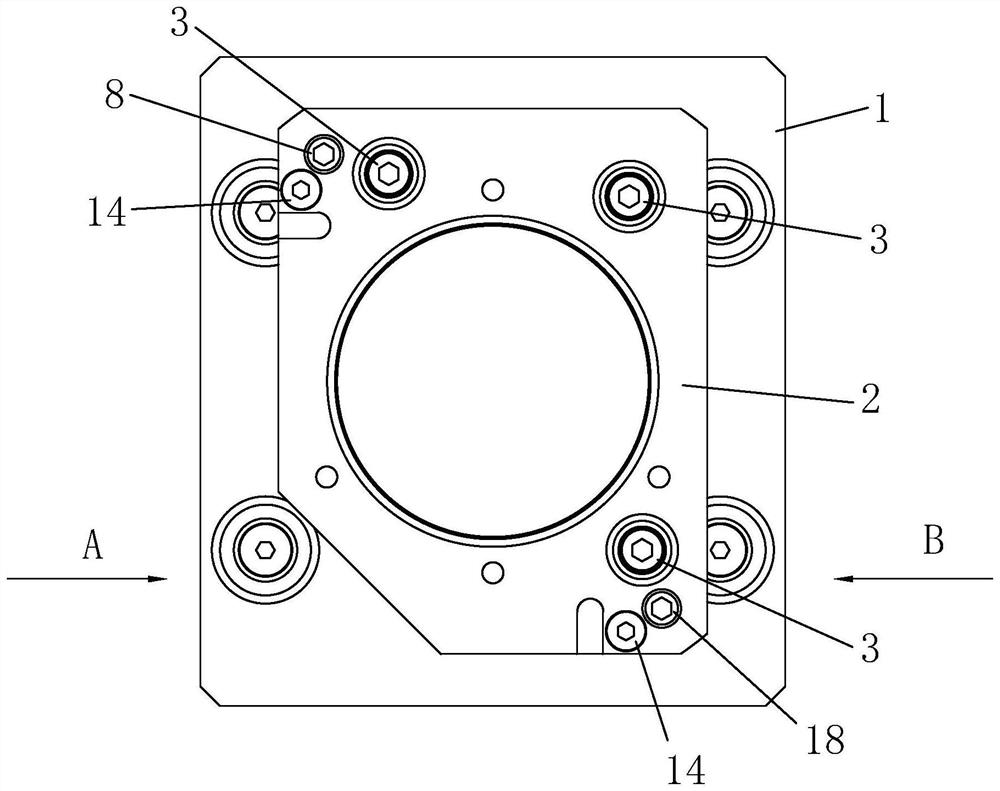
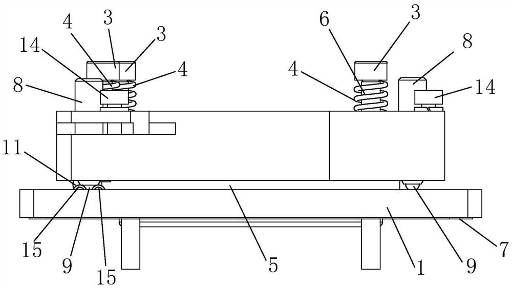
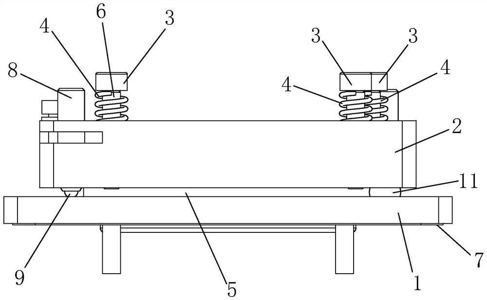
[0023] Such as Figure 1 to Figure 4 Shown, for the present invention can eliminate the laser reflector base of machine movement to produce resonance effect, comprise base plate 1, reflector base 2, fixing bolt 3 and spring 4, the afterbody of fixing bolt 3 passes through reflector base 2 and connects with base plate 1 Threaded connection, the spring 4 is sleeved on the fixing bolt 3, and the spring 4 is arranged between the head of the fixing bolt 3 and the reflector seat 2. Through the setting of the spring 4 and the fixing bolt 3, the connection between the bottom plate 1 and the reflector seat 2 is realized. At the same time, this structure is used to connect, and the elastic force of the compression spring 4 and the reaction of the screw tension can be used to directly eliminate the phenomenon that occurs when the machine is moving. The optical path swing and offset phenomenon caused by the transmission vibration of the advanced mechanism ensures the final focus stability...


PUM


Abstract

The invention discloses a laser reflector seat capable of eliminating a resonance effect generated by machine motion. The laser reflector seat comprises a bottom plate, a reflector seat, a fixing bolt and a spring. The tail part of the fixing bolt penetrates through the reflector seat and is in threaded connection with the bottom plate, the spring is arranged on the fixing bolt, and the spring is arranged between the head part of the fixing bolt and the reflector seat. And through the arrangement of the spring and the fixing bolt, the connection between the bottom plate and the reflector seat is realized. According to the invention, the phenomenon of light path swing offset caused by mechanism transmission vibration during machine motion can be eliminated, and the final focusing stability after laser light path transmission is ensured.

Description

technical field [0001] The invention belongs to the technical field of laser light path design, and in particular relates to a laser mirror seat capable of eliminating the resonance effect generated by machine movement. Background technique [0002] All domestic laser optical paths are directly fixed with a fixture or an adhesive lens holder. Although the optical path can be adjusted, it cannot offset the vibration effect and long-term Optical transmission distance. Therefore, most laser equipment factories directly use the least and shortest mirror group to design the laser light path. When the laser is installed on the side of the machine tool, in order to meet the design requirements of the laser optical path, more than 6 sets of mirror groups are required to ensure the optical path. However, due to the movement of the machine and the long-distance optical path transmission, the optical path shifts and shakes, which will cause focus point shift ghosting at the focus pos...

Claims


Application Information

Patent Timeline
Patent Type & Authority Applications(China)
IPC IPC(8): G02B7/198
CPCG02B7/198
Inventor 甘田黄明宏陈重光
Owner 世一激光设备(绍兴)有限公司
Learn More