Microfluidic detection system and detection method thereof
A detection system and microfluidic technology, applied in the direction of measuring devices, color/spectral characteristic measurement, material analysis through optical means, etc., can solve the zero drift of the detection circuit, the influence of the ambient temperature of the PD receiver, and the fluctuation of the light intensity of the light source and other issues to achieve the effect of reducing damping oscillation
- Summary
- Abstract
- Description
- Claims
- Application Information
AI Technical Summary
Problems solved by technology
Method used
Image
Examples
Embodiment 1
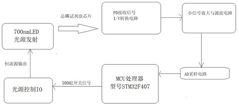
[0043] Provide a microfluidic detection system, such as figure 1 As shown, wherein the system includes:
[0044] MCU processor, light source control IO, 700nm characteristic frequency conversion light source control circuit, total phosphorus reagent plate chip, PD receiving circuit, small signal amplification and filtering circuit and AD sampling circuit;
[0045] The MCU processor is connected to the light source control IO, and is used to send a switch signal to the light source control IO;
[0046] The light source control IO is connected to the 700nm characteristic frequency conversion light source control circuit for receiving the switch signal and outputting it to the 700nm characteristic frequency conversion light source control circuit through the controllable signal switch DD1 constant current source;
[0047] The 700nm characteristic frequency conversion light source control circuit is used to receive the high and low level signals output by the controllable signal ...
Embodiment 2
[0066] A detection method is provided, which adopts the microfluidic detection system as described in Embodiment 1, such as Figure 5 As shown, including the following steps:
[0067] S1. The MCU processor controls the controllable signal switch DD1 to output 500HZ high and low level signals;
[0068] S2. The signal is output to the 700nm characteristic frequency conversion light source control circuit through the light source control IO, and the PD receiving circuit receives the light source signal strength emitted by the 700nm characteristic frequency conversion light source control circuit and passes through the total phosphorus reagent disc chip, and converts it into a small The current signal is output to the AD sampling circuit through the small signal amplification and filtering circuit to obtain the original signal data;
[0069] S3. The obtained original signal data is processed by a prime factor numerical transformation algorithm, and the voltage signal value at ADC...
PUM
 Abstract
Description
Claims
Application Information
 - R&D
- Intellectual Property
- Life Sciences
- Materials
- Tech Scout
- Unparalleled Data Quality
- Higher Quality Content
- 60% Fewer Hallucinations
Browse by: Latest US Patents, China's latest patents, Technical Efficacy Thesaurus, Application Domain, Technology Topic, Popular Technical Reports.
© 2025 PatSnap. All rights reserved.Legal|Privacy policy|Modern Slavery Act Transparency Statement|Sitemap|About US| Contact US: help@patsnap.com


