Full-automatic temperature control system of glass production line annealing kiln
A temperature control system and glass production line technology, applied in the field of glass technology, can solve problems such as temperature fluctuations and air valve damage, and achieve the effects of improving the yield and yield and reducing costs.
- Summary
- Abstract
- Description
- Claims
- Application Information
AI Technical Summary
Problems solved by technology
Method used
Image
Examples
Embodiment 1
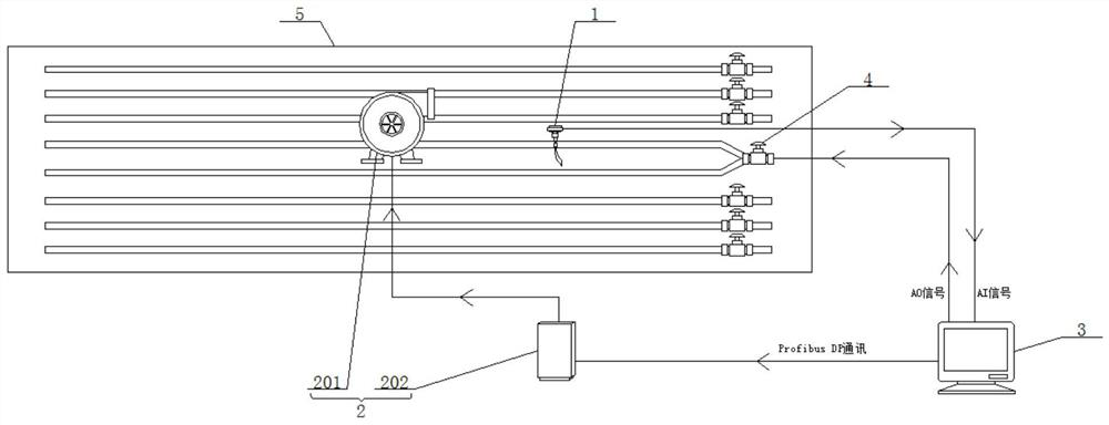
[0036] see figure 1 , the present invention provides a technical solution:
[0037] A fully automatic temperature control system for an annealing kiln in a glass production line, including an intermediate thermocouple 1, an air supply module 2, a main control module 3 and an air valve 4, the intermediate thermocouple 1, the air supply module 2, and the air valve 4 are respectively connected to the main control module 3 electrical connections;
[0038] The middle thermocouple 1 is arranged on the annealing kiln plate 5, and the middle thermocouple 1 is used to detect the temperature in the annealing kiln, and feeds back to the main control module 3 in real time. The measured object is in direct contact, not affected by the intermediate medium, the measurement accuracy is high, and its measurement range is wide, which well covers the temperature range of the annealing kiln. At the same time, the K-type thermocouple has a simple structure, and it is very convenient for on-site m...
Embodiment 2
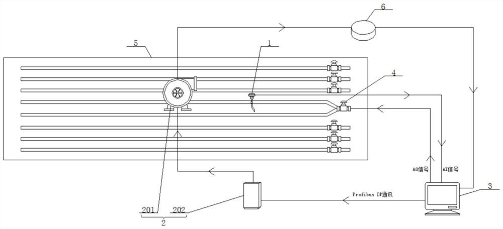
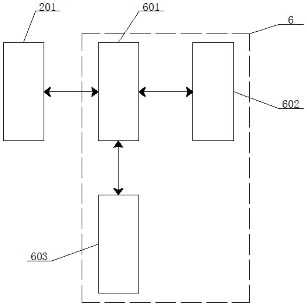
[0045] see figure 2 and image 3 , the difference from Example 1 is:
[0046] It also includes a fan fault detection module 6, which is electrically connected to the fan 201 and the main control module 3 respectively, and is used to detect the working status of the fan 201 and give a fault alarm when the fan 201 is abnormal.
[0047] The fan fault detection module 6 includes a fan status diagnosis unit 601, a fault alarm unit 602 and a fan status indication unit 603;
[0048] The fan status diagnosis unit 601 is electrically connected to the fan 201, and is used to receive the start-stop and frequency signals output by the fan 201, and convert the start-stop and frequency signals into fan status diagnostic signals;
[0049] The fault alarm unit 602 is electrically connected with the fan status diagnosis unit 601 and the main control module 3 respectively, and is used to receive the fan status diagnostic signal, and judge whether to send a fault alarm signal after processing...
Embodiment 3
[0054] see Figure 4 , the difference from Example 1 is:
[0055] The main control module 3 includes a sampling unit 301 and a fan control unit 302;
[0056] The sampling unit 301 is electrically connected to the frequency converter 202, and is used to acquire the voltage sampling value of the frequency converter 202;
[0057] The fan control unit 302 is electrically connected with the sampling unit 301, and is used to receive the voltage sampling value, count the effective zero-crossing points of the voltage sampling value, obtain the count value within a preset unit time, and output a control signal to the fan 201 to control the fan. 201 start operation.
[0058] The sampling unit 301 includes a voltage divider circuit and a filter circuit; the voltage divider circuit includes a plurality of voltage divider resistors connected in series; the filter circuit includes a filter capacitor, the first end of the filter capacitor is electrically connected to the voltage divider ci...
PUM
 Abstract
Description
Claims
Application Information
 - R&D
- Intellectual Property
- Life Sciences
- Materials
- Tech Scout
- Unparalleled Data Quality
- Higher Quality Content
- 60% Fewer Hallucinations
Browse by: Latest US Patents, China's latest patents, Technical Efficacy Thesaurus, Application Domain, Technology Topic, Popular Technical Reports.
© 2025 PatSnap. All rights reserved.Legal|Privacy policy|Modern Slavery Act Transparency Statement|Sitemap|About US| Contact US: help@patsnap.com


