
Self-locking mechanism, motor and linear actuator

A technology of self-locking and driving shafts, which is applied in the field of self-locking mechanisms, motors and linear actuators. It can solve the problems of self-locking performance decline, increase the force bearing surface of worm gear, reduce friction coefficient, etc., and achieve stable self-locking performance. Effect

Active Publication Date: 2021-11-16
ZHEJIANG JIECHANG LINEAR MOTION TECH
View PDF8 Cites 1 Cited by
  • Summary
  • Abstract
  • Description
  • Claims
  • Application Information

AI Technical Summary

Problems solved by technology

However, in the electric lift table, due to the increased load, the force surface of the worm wheel will eventually increase
The force load of the worm wheel becomes larger, which leads to the decrease of the friction force of the worm wheel after a period of load on the worm wheel of the movement, resulting in a decrease in self-locking performance
The principle of torsion spring self-locking is similar. The material of the torsion spring seat is POM100P. When it is stressed with the metal torsion spring, the torsion spring seat will reduce the friction coefficient after running for a period of time, resulting in a decline in self-locking performance.

Method used


Image

  • Self-locking mechanism, motor and linear actuator
  • Self-locking mechanism, motor and linear actuator
  • Self-locking mechanism, motor and linear actuator

Examples


Embodiment Construction

[0042] The technical solutions of the embodiments of the present invention will be explained and described below in conjunction with the accompanying drawings of the embodiments of the present invention, but the following embodiments are only preferred embodiments of the present invention, not all of them. Based on the examples in the implementation manners, other examples obtained by those skilled in the art without making creative efforts all belong to the protection scope of the present invention.

[0043] In describing the present invention, it should be understood that the terms "center", "longitudinal", "transverse", "length", "width", "thickness", "upper", "lower", "front", " The orientations or positional relationships indicated by "rear", "left", "right", "vertical", "horizontal", "top", "bottom", "inner", "clockwise", "counterclockwise" are based on the attached The orientation or positional relationship shown in the figure is only for the convenience of describing t...


PUM


Abstract

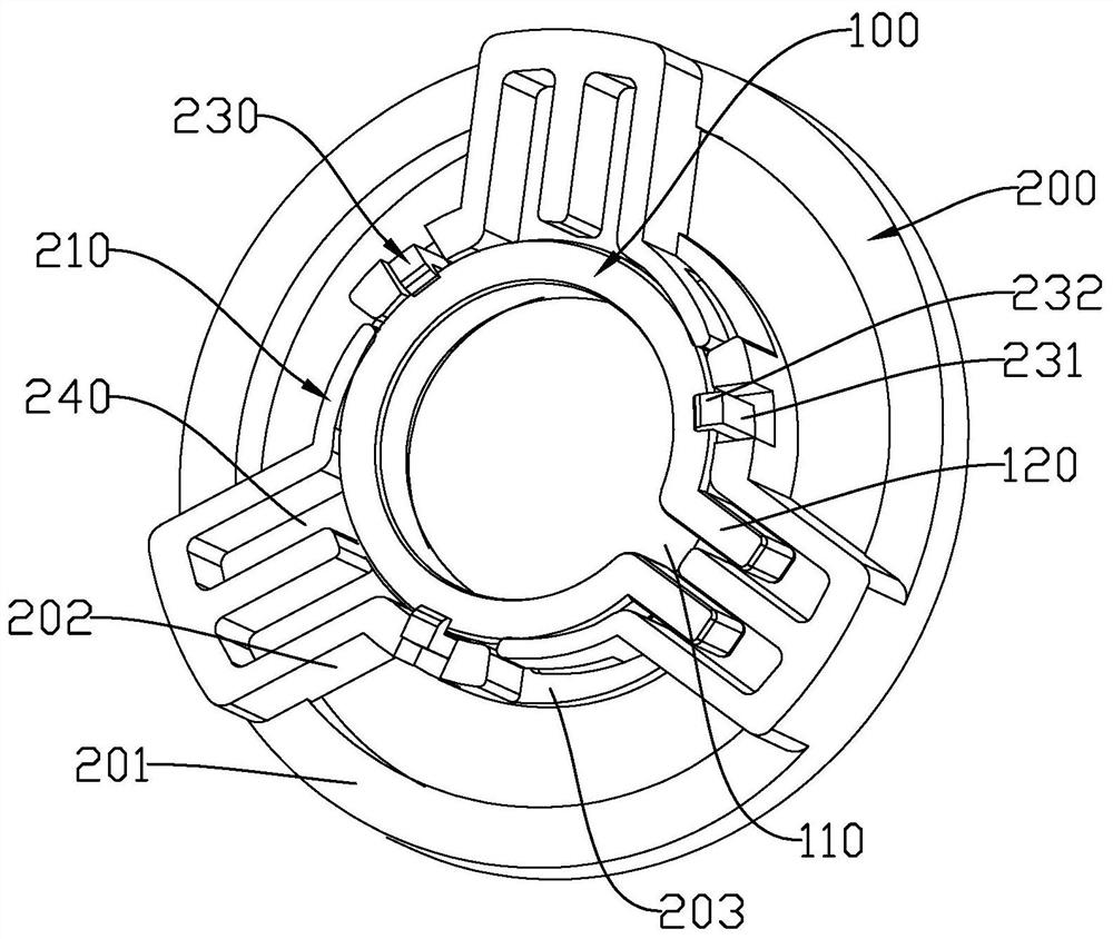
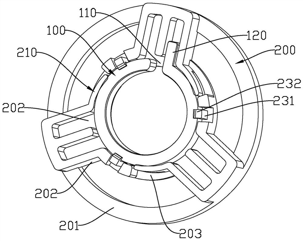
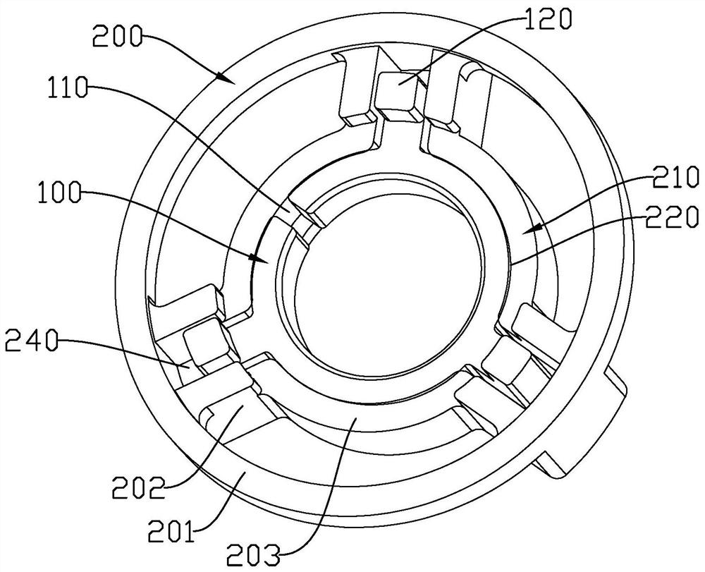
The invention discloses a self-locking mechanism, a motor and a linear actuator, and belongs to the field of self-locking mechanisms. The self-locking mechanism has stable self-locking performance and comprises a friction ring and a mounting seat, the mounting seat is fixed relative to the friction ring, a notch is formed in the friction ring, and the friction ring is arranged on a rotary body needing to be braked in a sleeving mode. A mounting part used for mounting the friction ring is defined on the mounting seat, and the mounting part extrudes the friction ring in the direction of the notch so as to apply braking force to the rotary body.

Description

【Technical field】 [0001] The invention relates to the field of self-locking mechanisms, in particular to self-locking mechanisms, motors and linear actuators. 【Background technique】 [0002] Commonly used electric lifting columns, through the principle of self-locking of the movement, self-locking of the screw drive, and self-locking of the torsion spring. The lead angle of the movement self-locking through the transmission of the worm and the worm wheel is smaller than the equivalent friction angle. The commonly used worm material 40Cr and worm gear material POM100P form a certain friction coefficient, which is about 0.1-0.15. However, in the electric lift table, due to the increased load, the force surface of the worm wheel will eventually increase. The force load of the worm wheel becomes larger, which leads to the reduction of the friction of the worm wheel after a period of load on the worm wheel of the movement, resulting in a decrease in self-locking performance. T...

Claims


Application Information

Patent Timeline
Patent Type & Authority Applications(China)
IPC IPC(8): B66F13/00F16D49/00F16D65/06
CPCB66F13/00F16D49/00F16D65/06F16D49/20F16D65/18F16D2121/24
Inventor 岑余杰唐诗轶
Owner ZHEJIANG JIECHANG LINEAR MOTION TECH
Learn More