
Four-side centering clamp and batch clamping system

A technology of dividing the fixture and dividing the slot, applied in the direction of clamping, positioning device, manufacturing tool, etc., can solve the time of clamping and calibration and the time of external clamping, the requirement of high technical level of workers, and the processing of machine tools. Problems such as low part efficiency, to reduce the clamping time, improve the processing efficiency, and shorten the time-consuming effect

Pending Publication Date: 2021-11-16
WUHAN LIANSU PRECISION MOLD
View PDF17 Cites 5 Cited by
  • Summary
  • Abstract
  • Description
  • Claims
  • Application Information

AI Technical Summary

Problems solved by technology

Each part is clamped through this process, which takes a long time for the operator and requires a high technical level of the workers. The time for clamping and calibrating the mold parts and the external clamping time for the mold parts are relatively long, resulting in the failure of the machine tool to process the parts. low efficiency
Existing fixtures with split clamping do not exist, only some simple workpiece fixtures for automobiles, such as the Chinese patent with the announcement number CN210878699U and the announcement date of 2020.6.30: a fixture for auto parts. The side screw drives the jaws to clamp the workpiece, which is not suitable for the split clamping of the above parts, so it is urgent to design a fixture for split clamping

Method used


Image

  • Four-side centering clamp and batch clamping system
  • Four-side centering clamp and batch clamping system
  • Four-side centering clamp and batch clamping system

Examples


Embodiment 1

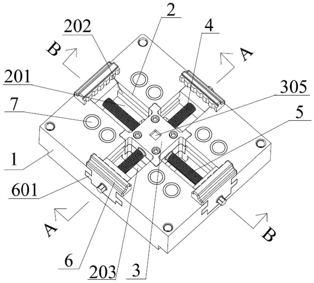
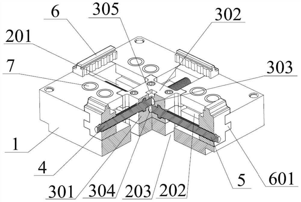
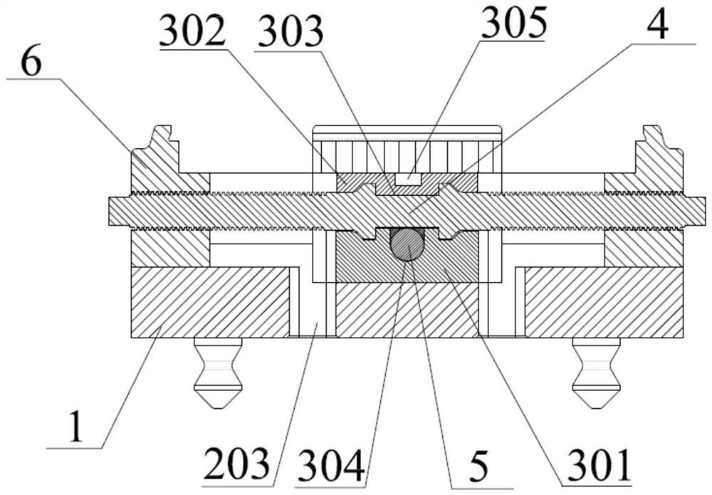
[0034] Such as Figure 1-Figure 4 As shown, a four-sided centering fixture includes a base 1, a cross groove 2 is provided on the base 1, a screw positioning block 3 is provided at the center of the cross groove 2, and the screw positioning block 3 is threaded with a first screw rod 4 and The second screw mandrel 5, the first screw mandrel 4 and the second screw mandrel 5 are arranged in a dislocation up and down, in the present embodiment the first screw mandrel 4 is placed above the second screw mandrel 5, certainly the first screw mandrel 4 Placed below the second screw mandrel 5, and the first screw mandrel 4 and the second screw mandrel 5 are placed in the cross groove 2 in a cross shape, and both ends of the first screw mandrel 4 and the second screw mandrel 5 are threadedly connected with Locking block 6, locking block 6 is slidingly connected with cross groove 2, the thread directions of both ends of the first screw rod 4 and the second screw rod 5 are opposite, one en...


PUM


Abstract

The invention discloses a four-side centering clamp and a batch clamping system. The four-side centering clamp comprises a base, a cross-shaped groove is formed in the base, a lead screw positioning block is arranged in the center of the cross-shaped groove, a first lead screw and a second lead screw are inserted into the lead screw positioning block in a threaded mode, and the first lead screw and the second lead screw are arranged in an up-down staggered mode. The first lead screw and the second lead screw are arranged in the cross-shaped groove in a cross-shaped mode, the two ends of the first lead screw and the two ends of the second lead screw are in threaded connection with locking blocks, the locking blocks are in sliding connection with the cross-shaped groove, and the directions of the threads at the two ends of the first lead screw and the threads at the two ends of the second lead screw are opposite. The double-shaft automatic centering locking technology is adopted, automatic centering and mold workpiece locking outside a machine tool can be achieved in the machining process of the machine tool, the whole process is short in consumed time, the requirement for the technical level of workers is not high, operation is easy, the workpiece clamping time can be effectively shortened, and the machining efficiency of the machine tool is improved.

Description

technical field [0001] The invention relates to the technical field of numerical control machining, in particular to a four-sided centering fixture and a batch clamping system. Background technique [0002] The traditional part processing method is to manually shake the handwheel of the CNC machine tool to drive the pointer meter adsorbed on the spindle. By reading the jump value on the pointer meter, it is determined whether the X, Y reference of the workpiece is parallel to the X, Y of the machine tool, and repeated adjustments Workpiece position until the runout value on the pointer table does not exceed the limit value, then touch the four sides of the workpiece with the centering rod on the spindle, and manually calculate half of the X and Y dimensions of the part according to the data on the CNC panel on the machine tool Value, get the zero position of the coordinates X, Y, and Z of the part relative to the machine tool, and then lock the part with a code iron or a dis...

Claims


Application Information

Patent Timeline
Patent Type & Authority Applications(China)
IPC IPC(8): B23Q3/06
CPCB23Q3/06
Inventor 王全喜
Owner WUHAN LIANSU PRECISION MOLD
Learn More