Magnetic coupler with electromagnetic slip damping

A technology of magnetic coupling and slip, applied in electric brake/clutch, permanent magnetic clutch/brake, asynchronous induction clutch/brake, etc., can solve the problem that magnetic coupling cannot satisfy soft start and high efficiency at the same time, Achieve the effect of light weight, high efficiency and high utilization rate of magnetic steel

Pending Publication Date: 2021-11-12
JIANGSU MAGNET VALLEY TECH
View PDF0 Cites 0 Cited by
  • Summary
  • Abstract
  • Description
  • Claims
  • Application Information

AI Technical Summary

Problems solved by technology

[0003] The technical problem to be solved by the present invention is to overcome the defect that the magnetic coupler in the prior art cannot satisfy soft start and high efficiency at the same time, so as to provide a magnetic coupler that can realize soft start and ensure high efficiency operation

Method used


Image

  • Magnetic coupler with electromagnetic slip damping
  • Magnetic coupler with electromagnetic slip damping
  • Magnetic coupler with electromagnetic slip damping

Examples


Embodiment 1

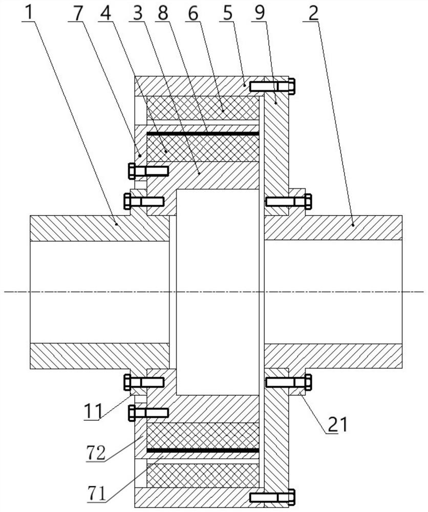
[0040] refer to figure 1 , a magnetic coupling with electromagnetic slip damping provided by the present invention, comprising:

[0041] The first connecting shaft 1 is suitable for connecting with the driving end;

[0042] The second connecting shaft 2 is adapted to be connected to the load end, the second connecting shaft 2 is coaxial with the first connecting shaft 1 and independently arranged;

[0043] The inner permanent magnet carrier 3 is coaxially fixed on the first connecting shaft 1, and the inner permanent magnet 4 is fixed on the outer peripheral surface of the inner permanent magnet carrier 3;

[0044] The outer permanent magnet carrier 5 is coaxially fixed on the second connecting shaft 2. The outer permanent magnet carrier 5 is a cylindrical structure and is sleeved on the outside of the inner permanent magnet carrier 3. The inner wall of the outer permanent magnet carrier 5 is fixed with An outer permanent magnet 6, leaving a gap between the outer permanent m...

Embodiment 2

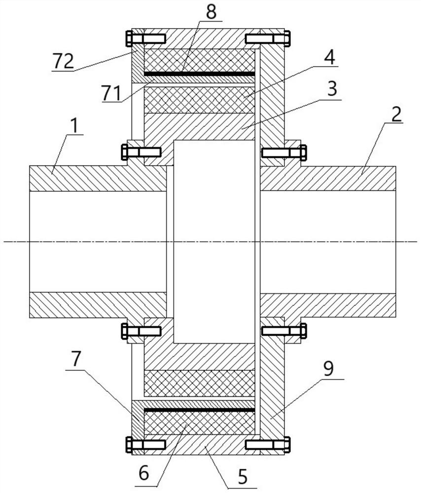
[0072] refer to figure 2 , a magnetic coupling with electromagnetic slip damping provided in this embodiment differs from Implementation 1 only in that:

[0073] In this embodiment, the conductor ring 7 is relatively fixed on the outer permanent magnet carrier 5 , and the heat insulating ring 8 is located between the conductor ring 7 and the outer permanent magnet 6 .

[0074] In other embodiments, the conductor ring 7 can also be fixed on the second connecting shaft 2 through a common connecting structure.

[0075] It is worth noting that no matter whether the conductor ring 7 is fixed relative to the inner permanent magnet 4 or relative to the outer permanent magnet 6, since the inner permanent magnet 4 and the outer permanent magnet 6 have relative rotation, the conductor ring 7 should be connected to another permanent magnet. Leave a gap between them to avoid interfering with the rotation. E.g figure 2 The middle conductor ring 7 is fixed on the outer permanent magnet...


PUM


Abstract

The invention relates to the technical field of mechanical transmission, and concretely relates to a magnetic coupler with electromagnetic slip damping. According to the scheme, the magnetic coupler comprises: a first connecting shaft; a second connecting shaft, wherein the second connecting shaft and the first connecting shaft are coaxial and are independently arranged; an inner permanent magnet carrier coaxially fixed on the first connecting shaft, wherein an inner permanent magnet is fixed on the peripheral surface of the inner permanent magnet carrier; an outer permanent magnet carrier coaxially fixed on the second connecting shaft, wherein the outer permanent magnet carrier is of a cylindrical structure and sleeves the outer side of the inner permanent magnet carrier, an outer permanent magnet is fixed on the inner wall of the outer permanent magnet, and a gap is reserved between the outer permanent magnet and the inner permanent magnet; and a conductor ring positioned in the gap and is relatively fixed on the inner permanent magnet carrier or the outer permanent magnet carrier. Through the arrangement of the conductor ring, soft start can be realized through asynchronous transmission during heavy load, and high-efficiency work can also be realized through synchronous transmission.

Description

technical field [0001] The invention relates to the technical field of mechanical transmission, in particular to a magnetic coupling with electromagnetic slip damping. Background technique [0002] At present, the magnetic couplings (also known as permanent magnetic couplings or permanent magnetic couplings) used in the machinery industry mainly include synchronous permanent magnet transmission and asynchronous permanent magnet transmission. Synchronous permanent magnet transmission has no temperature rise and high transmission efficiency during the working process, but it is easy to slip at full speed when encountering an impact load, or it is easy to cause full speed slipping when the starting torque is large when starting with load; during the working process of asynchronous permanent magnet transmission There is a phenomenon of temperature rise and heating, and the efficiency is low, but it can start with a certain slip when starting, and the starting characteristics are...

Claims


Application Information

Patent Timeline
Patent Type & Authority Applications(China)
IPC IPC(8): H02K49/10H02K49/04
CPCH02K49/106H02K49/043
Inventor 杨可银徐俊峰
Owner JIANGSU MAGNET VALLEY TECH
Why Eureka
Try Eureka