
Laser radar

A laser radar and laser technology, applied in the field of optical ranging, can solve problems such as limited vertical resolution, reduced duty cycle of the light-emitting surface, shrinking the transmitting module and/or detecting module, etc., to improve the ranging capability and power Density, the effect of reducing background light noise power

Pending Publication Date: 2021-11-12
HESAI TECH CO LTD
View PDF0 Cites 5 Cited by
  • Summary
  • Abstract
  • Description
  • Claims
  • Application Information

AI Technical Summary

Problems solved by technology

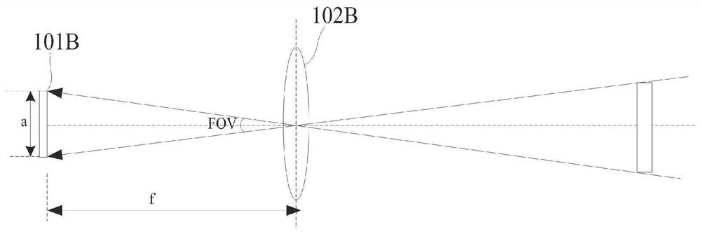
In order to keep the lidar machine at a suitable height even when it covers a large field of view (such as 105°), the focal length of the emission module and / or detection module has to be reduced, such as replacing the one with a shorter focal length. Optical devices, etc., which will not only reduce the duty cycle of the light-emitting surface but also limit the vertical vertical resolution

Method used


Image

  • Laser radar
  • Laser radar
  • Laser radar

Examples


Embodiment Construction

[0046] Embodiments of the present application are described below through specific examples, and those skilled in the art can easily understand other advantages and effects of the present application from the content disclosed in this specification. The present application can also be implemented or applied in different specific implementation modes, and various modifications or changes can be made to the details in this specification based on different viewpoints and applied systems without departing from the spirit of the present application. It should be noted that, in the case of no conflict, the embodiments in the present application and the features in the embodiments can be combined with each other.

[0047] The embodiments of the present application will be described in detail below with reference to the accompanying drawings, so that those skilled in the art of the present application can easily implement them. The present application can be embodied in various forms,...


PUM


Abstract

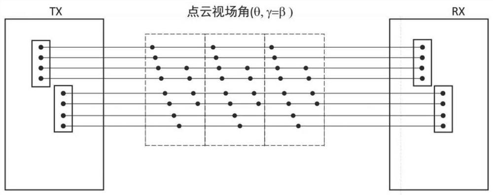
The invention provides a laser radar which comprises a laser array arranged in a linear array or an area array, a focal plane arranged on a first optical assembly, and the first optical assembly arranged on a transmitting light path and forming an equivalent focal length larger than the focal length of a main lens group unit of a transmitting end. And / or an optical detector array arranged in a linear array or an area array and arranged on a focal plane of a second optical assembly, and the second optical assembly is arranged on a receiving optical path and forms an equivalent focal length larger than the focal length of the main lens group unit at the receiving end. According to the embodiment of the invention, the power density in the point cloud field angle area is improved through the arrangement of the first optical assembly of the light transmitting end, and / or the background light noise power in the point cloud field angle area is reduced through the arrangement of the second optical assembly of the receiving end, so that the distance measurement capability of the radar can be improved.

Description

technical field [0001] The present application relates to the technical field of optical ranging, in particular to laser radar. Background technique [0002] Lidar is a detection device that calculates the distance of an object by emitting a laser and detecting the echo signal reflected after the laser reaches the surface of the object. Therefore, the lidar needs to include two parts: a light emitting (Transmitter X) element and a light detecting (Receiver X) element, which can be called a light emitting module and a light detecting module. [0003] The laser radar includes an optical system, which is distributed in the light emission module and the light detection module. For example, the light emission module includes a main lens group for collimating the emission signal of the laser, etc., and the light detection module includes a lens for converging the echo signal to the detector receiving lens etc. For the light-emitting module (or light-detecting module), its field ...

Claims


Application Information

Patent Timeline
Patent Type & Authority Applications(China)
IPC IPC(8): G01S17/08G01S7/481
CPCG01S17/08G01S7/481
Inventor 陈杰向少卿
Owner HESAI TECH CO LTD
Learn More