An electrolytic refining tank surface operation to prevent personnel from falling into the tank protection device
An electrolytic refining and protection device technology, applied in the field of electrolytic refining, can solve the problems of easy rust, large occupied area, inconvenient equipment assembly and disassembly, etc., and achieve the effect of solving potential safety hazards, reducing occupied area, and enhancing operating efficiency
- Summary
- Abstract
- Description
- Claims
- Application Information
AI Technical Summary
Problems solved by technology
Method used
Image


Examples
Embodiment 1
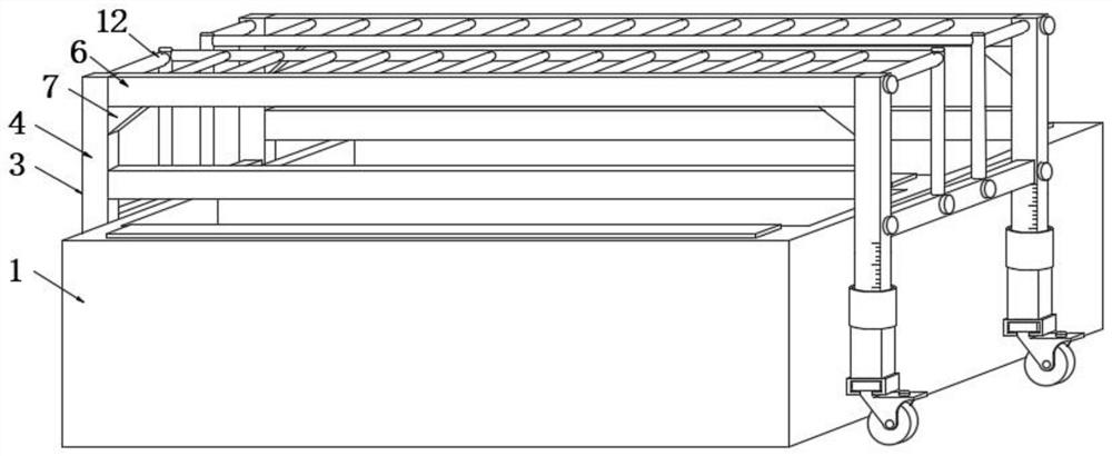
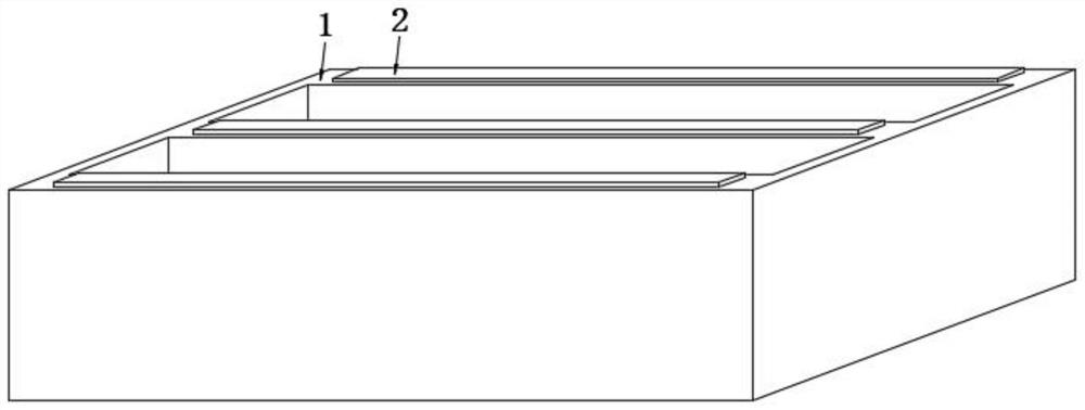
[0035] see Figure 1-6 As shown, the present invention is an electrolytic refining tank surface operation preventing personnel from falling into the tank, including an electrolytic tank 1, and copper bars 2 are fixedly connected on both sides of the upper surface of the electrolytic tank 1. During the cleaning process, the worker needs to The copper bar 2 is polished, and a protection mechanism 3 is provided outside the electrolytic cell 1. The protection mechanism 3 includes a load-bearing rod 4, and a fixed rod 6 and a positioning cross rod 5 are respectively fixedly connected between the two load-bearing rods 4 from top to bottom. The fixed rod 6 fixes the two load-bearing rods 4 together, and the positioning cross rod 5 increases the stability between the two load-bearing rods 4. The positioning cross rod 5 and the fixed rod 6 are fixed by welding to make the whole more stable. , the side of the fixed rod 6 close to the positioning cross rod 5 is fixedly connected with a tri...
Embodiment 2
[0038] like Figure 7-8 As shown, the lower end of the load-bearing rod 4 is externally sleeved with the support rod 10, and the external rotation of the support rod 10 is connected to the adjustment mechanism 9, and the end of the support rod 10 away from the adjustment mechanism 9 is fixedly connected to the universal wheel 11. The adjustment mechanism 9 includes an adjustment rotating tube 91 , adjust the internal rotation of the rotating tube 91 to connect the matching hollow tube 92, one end of the matching hollow tube 92 is fixedly connected with the support rod 10, the equipment is supported by the support rod 10, and the lower end of the load-bearing rod 4 is inserted into the matching hollow tube 92. , by observing the scale bar on the surface of the load-bearing rod 4 to control the height of the adjustment to ensure that the heights of the four load-bearing rods 4 are the same, improve the effect of the stability of the protection mechanism 3, and adjust the inner wa...
Embodiment 3
[0040] like Figure 1-8 As shown in the figure, the assembly and height adjustment of the equipment are carried out before work. The side of the guide pin 171 away from the buckle 2 16 is fixedly connected to the fixing frame 173. One end of the splicing rod 8 is fixedly connected to the inner wall of the splicing rod 8. During the assembly process, the buckle two 16 squeezes the guide pin 171, so that the guide pin 171 drives the fixing frame 173 to move to the outside of the splicing rod 8, and at the same time makes the limit spring 172 is elastically deformed, and the fixed frame 173 is rotated and connected to the guide wheel 174 on one side close to the electrolytic cell 1. The guide wheel 174 is positioned through the bearing rod 175, and the guide wheel 174 is at the same time close to the outside of the electrolytic cell 1. Then the protection mechanism 3 It is placed on the electrolytic cell 1 to be operated, and the protection mechanism 3 is designed with corrosion-...
PUM
 Abstract
Description
Claims
Application Information
 - R&D
- Intellectual Property
- Life Sciences
- Materials
- Tech Scout
- Unparalleled Data Quality
- Higher Quality Content
- 60% Fewer Hallucinations
Browse by: Latest US Patents, China's latest patents, Technical Efficacy Thesaurus, Application Domain, Technology Topic, Popular Technical Reports.
© 2025 PatSnap. All rights reserved.Legal|Privacy policy|Modern Slavery Act Transparency Statement|Sitemap|About US| Contact US: help@patsnap.com