
Automobile antenna support forming method

A molding method and technology for automotive antennas are applied in the field of stamping processing, which can solve the problems of complex structure and adverse effects of metal material flow, and achieve the effect of ensuring accuracy requirements.

Active Publication Date: 2021-11-12
苏州铭峰精密机械有限公司
View PDF41 Cites 1 Cited by
  • Summary
  • Abstract
  • Description
  • Claims
  • Application Information

AI Technical Summary

Problems solved by technology

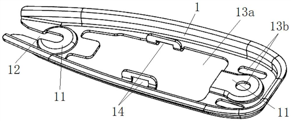
[0002] The structure of the car antenna support 1 is as follows figure 1 As shown, its structure is relatively complicated, and there are many convex hull structures 11 on it, and a gap 12 is cut out in one of the convex hull structures 11, and there are large through holes 13a and small through holes 13b in the middle, and the two sides of the large through holes 13a are There is a bent buckle hole 14
Because the existence of the large through hole 13a will bring a lot of adverse effects on the flow of metal materials

Method used


Image

  • Automobile antenna support forming method
  • Automobile antenna support forming method

Examples


Embodiment

[0028] like figure 1 and figure 2 Shown, a kind of automobile antenna support molding method of the present invention, the step comprises:

[0029] ① Cut out outer positioning holes 101 on both sides of the metal strip 100 . The outer positioning hole 101 is used as a positioning reference on the continuous part 106 to allow each stamping of the continuous die to locate the outer position.

[0030] ② Cut out the outer contour of the core part 104 on the metal strip 100 with a reserved amount of deformation, and let the core part 104 be connected to the continuous parts 106 on both sides of the metal strip 100 by means of several connecting materials 105 .

[0031] ③ Punch out the deformation reserved hole 103 in the middle of the core part 104 . The scope of the deformation reserved hole 103 is inside the scope of the large through hole 13a, but smaller. The purpose of this is to allow the middle material to flow outwards during the convex hulling process but not exceed th...


PUM


Abstract

The invention belongs to the technical field of stamping machining, and relates to an automobile antenna support forming method which comprises the steps of positioning hole punching, outer trimming, preformed hole punching, convex hull punching, groove punching, buckle hole punching, inner trimming, flanging and blanking. By means of the method, deformation machining of an automobile antenna support can be completed continuously and rapidly, and the precision requirement of each position can be met.

Description

technical field [0001] The invention relates to the technical field of stamping processing, in particular to a method for forming an automobile antenna support. Background technique [0002] The structure of the car antenna support 1 is as follows figure 1 As shown, its structure is relatively complicated, and there are many convex hull structures 11 on it, and a gap 12 is cut out in one of the convex hull structures 11, and there are large through holes 13a and small through holes 13b in the middle, and the two sides of the large through holes 13a are There are bent snap holes 14 . Because the existence of the large through hole 13a will bring many adverse effects to the flow of the metal material. These structures place high demands on the forming accuracy, so it is necessary to develop a process to rapidly process the automotive antenna mounts. Contents of the invention [0003] The main purpose of the present invention is to provide a method for forming an automobil...

Claims


Application Information

Patent Timeline
IPC IPC(8): B21D53/88B21D35/00
CPCB21D53/88B21D35/001B21D35/002Y02T10/40
Inventor 顾大明
Owner 苏州铭峰精密机械有限公司
Learn More