Pipe bending equipment and bent pipe machining method for inhibiting bent pipe from becoming elliptic
A processing method and pipe bending technology, which are applied in the field of pipe bending processing, pipe bending equipment and the suppression of ellipse pipe bending, can solve the problems of ellipticity tensile fracture, aggravated deformation, affecting the quality of aircraft and rocket products, etc., to avoid problems such as Tensile fracture, the effect of reducing ovality
- Summary
- Abstract
- Description
- Claims
- Application Information
AI Technical Summary
Problems solved by technology
Method used
Image
Examples
Embodiment 1
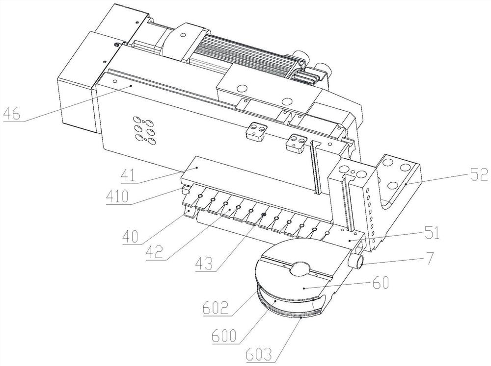
[0064] Such as figure 1 The numerically controlled pipe bending equipment shown to suppress the wrinkling and ellipse of the bent pipe includes a frame 1 and an automatic feeding and transferring device 2 installed on the frame 1, an anti-wrinkle mechanism 3, a supporting mechanism 4, a mold clamping device 5 and Bending mold mechanism 6, described automatic feeding transfer device 2 sends conduit 7 to anti-wrinkle mechanism 3, support mechanism 4, clamping mold device 5 and bending mold mechanism 6, and between anti-wrinkle mechanism 3, support mechanism 4, clamping mold The device 5 and the bending die mechanism 6 cooperate to complete the pipe bending operation of the conduit 7, wherein, before performing the pipe bending operation, the anti-wrinkle mechanism 3 and the bending die mechanism 6 are located on the right side of the conduit 7, and the support Mechanism 4 and mold clamping device 5 are located on the left side of conduit 7 .
[0065] In the embodiment of the pr...
Embodiment 2
[0178] The difference between this embodiment and the first embodiment is that the joint pressing block 42 and the guide seat 41 in the first embodiment are no longer used in this embodiment; instead, they are replaced by a mold guiding mechanism.
[0179] It is worth noting that the clamping mold 51 in this embodiment is not hinged to the mold guiding mechanism.
[0180] In the embodiment of the present invention, such as Figure 17 , Figure 18 , Figure 19 and Figure 20As shown, the mold guiding mechanism includes a mounting bracket 80 and a fourth driving member 81 installed on the frame 1, and a first guiding mold 82, a second guiding mold 83 and a first guiding mold 83 installed on the mounting bracket 80 from top to bottom. The third guide mold 84, the right end surface of the first guide mold 82 is provided with a linear first arc surface 820, and the right end surface of the second guide mold 83 is provided with a linear second arc surface 830. The right end surf...
Embodiment 3
[0189] The difference between the present embodiment and the first embodiment is that the joint pressing block 42 and the guide seat 41 in the first embodiment are no longer used in this embodiment; instead, the guide seat 90 is used instead.
[0190] It is worth noting that the mold clamping 51 in this embodiment is not hinged to the mold guide base 90 .
[0191] In this example, if Figure 21 and Figure 22 As shown, a number of second heating tubes 91 are also provided, and a number of parallel fourth installation holes 900 are also provided on the guide mold base 90. The fourth installation holes 900 are in the front and rear direction, and the number of second heating tubes 91 is installed in the fourth installation hole 900 .
[0192] Further preferably, a second temperature sensor is also provided, and the second temperature sensor is used to detect the temperature of the guide mold base 90 .
[0193] Further preferably, the material of the mold guide base 90 is high...
PUM
 Abstract
Description
Claims
Application Information
 - R&D
- Intellectual Property
- Life Sciences
- Materials
- Tech Scout
- Unparalleled Data Quality
- Higher Quality Content
- 60% Fewer Hallucinations
Browse by: Latest US Patents, China's latest patents, Technical Efficacy Thesaurus, Application Domain, Technology Topic, Popular Technical Reports.
© 2025 PatSnap. All rights reserved.Legal|Privacy policy|Modern Slavery Act Transparency Statement|Sitemap|About US| Contact US: help@patsnap.com


