Automatic assembling equipment for DBC (Direct Bonding Copper) board
An automatic assembly and equipment technology, applied in the assembly/disassembly of contact parts, etc., can solve the problems of inaccuracy, missing installation position of DBC board, etc., and achieve the effect of solving inaccurate installation position, solving missing installation, and improving assembly efficiency
- Summary
- Abstract
- Description
- Claims
- Application Information
AI Technical Summary
Problems solved by technology
Method used
Image
Examples
specific Embodiment 1
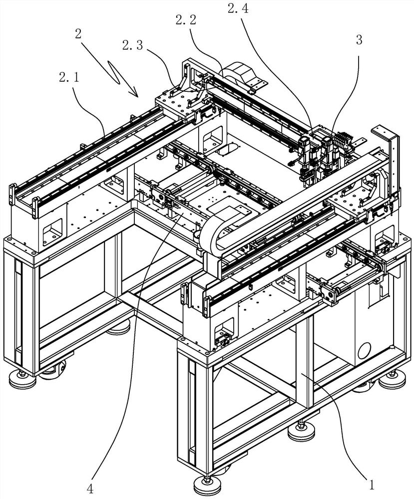
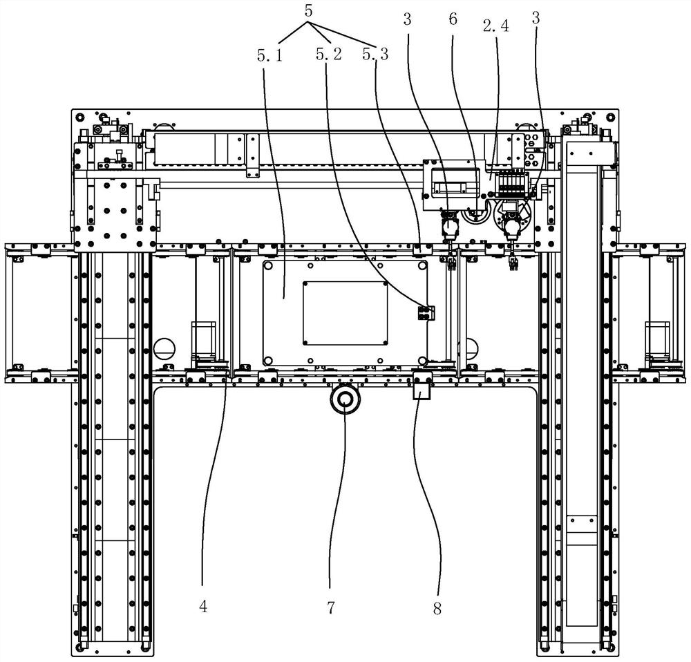
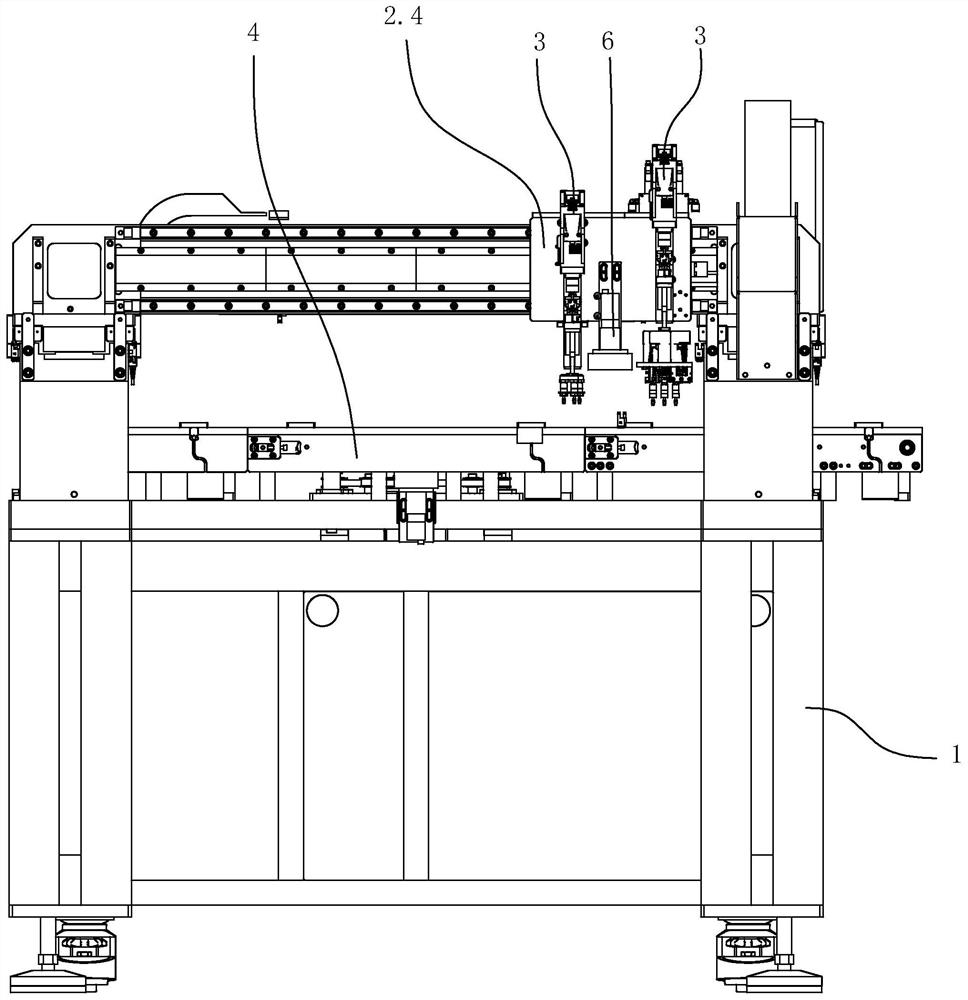
[0051] Specific embodiment one: as figure 1 , figure 2 , image 3 , Figure 4 , Figure 5 , Image 6 As shown, a DBC board automatic assembly equipment includes a frame 1, an IGBT module positioning tool 9, a mounting board 2.4 and a DBC board grabbing device 3. A two-axis manipulator 2 is arranged on the frame, and the two-axis manipulator is used to drive the mounting plate to move in the X-axis and Y-axis directions. Specifically, the two-axis manipulator includes a longitudinal guide rail 2.1 arranged on the frame, a translation beam 2.2 that translates along the longitudinal guide rail, a longitudinal linear module for driving the translation beam to translate along the longitudinal guide rail, and a transverse guide rail 2.3 arranged on the translation beam. With the horizontal linear module, the mounting plate slides along the horizontal guide rail, and the horizontal linear module drives the mounting plate to translate along the horizontal guide rail. Parallel,...
specific Embodiment 2
[0065] Specific embodiment two, all the other structures of this embodiment refer to specific embodiment one, and its difference is:
[0066] Such as figure 1 , figure 2 , image 3 , Figure 4 As shown, a DBC board automatic assembly equipment also includes a conveying track 4 and a pallet lifting device 5 arranged on the frame. The conveying track is distributed horizontally. In this embodiment, the conveying direction of the conveying track is parallel to the transverse guide rail.
[0067] The IGBT module positioning tooling 9 includes a pallet 9.1 and several positioning components 9.2 arranged on the pallet, and the positioning components are used for the IGBT module. The positioning assembly includes the IGBT module positioning pin 9.21 arranged on the tray. The IGBT module has a process hole that matches the positioning pin. The IGBT module is supported on the tray. Positioned on the positioning component. One positioning component positions one IGBT module. T...
specific Embodiment 3
[0069] Specific embodiment three, all the other structures of this embodiment refer to specific embodiment one, and its difference is:
[0070] The support platform on the frame and the tray positioning pin arranged on the support platform.
[0071] Such as Figure 4As shown, the IGBT module positioning tool 9 includes a tray 9.1 and a number of positioning components 9.2 arranged on the tray. The positioning component is used for the IGBT module. The positioning component includes an IGBT module positioning pin 9.21 set on the tray. The matching process hole, the IGBT module is supported on the tray, and the process hole of the IGBT module cooperates with the positioning pin of the IGBT module to realize the positioning of the IGBT module on the positioning component. One positioning component positions one IGBT module.
[0072] The tray is supported on the supporting platform, and the tray is provided with a positioning hole matched with the positioning pin of the tray. I...
PUM
 Abstract
Description
Claims
Application Information
 - R&D
- Intellectual Property
- Life Sciences
- Materials
- Tech Scout
- Unparalleled Data Quality
- Higher Quality Content
- 60% Fewer Hallucinations
Browse by: Latest US Patents, China's latest patents, Technical Efficacy Thesaurus, Application Domain, Technology Topic, Popular Technical Reports.
© 2025 PatSnap. All rights reserved.Legal|Privacy policy|Modern Slavery Act Transparency Statement|Sitemap|About US| Contact US: help@patsnap.com


