
Automatic assembly machine of stationary contact and tension screw stud

A static contact and assembly machine technology, applied in metal processing, metal processing equipment, manufacturing tools, etc., can solve problems such as low production efficiency, unstable use, and unsafety, and save manpower and production time. The effect of small floor area and improving work efficiency

Inactive Publication Date: 2018-11-13
王远志
View PDF0 Cites 10 Cited by
  • Summary
  • Abstract
  • Description
  • Claims
  • Application Information

AI Technical Summary

Problems solved by technology

In the assembly of high-voltage switchgear, it is often necessary to assemble the static contact element and the static contact base first, and to assemble the static contact with the base, the static contact and the clamping screw must first be assembled together, and then the static contact with the base Assembly, if the assembly is not in place and the quality of the finished product is not good, as the number of uses increases, the static contact will gradually wear out and loosen with the base, resulting in unstable and unsafe use. It is very time-consuming if the assembly is done manually It is laborious, and the production efficiency is not high, and the quality of finished products is also uneven

Method used


Image

  • Automatic assembly machine of stationary contact and tension screw stud
  • Automatic assembly machine of stationary contact and tension screw stud
  • Automatic assembly machine of stationary contact and tension screw stud

Examples


Embodiment Construction

[0020] Below in conjunction with accompanying drawing and embodiment of description, specific embodiment of the present invention is described in further detail:

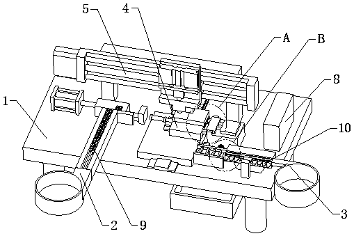
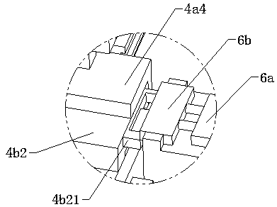
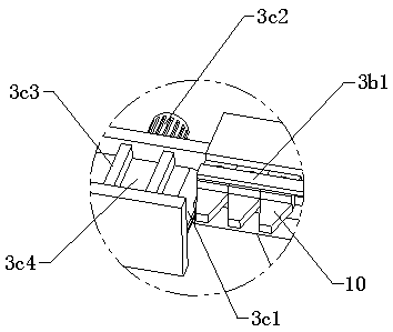
[0021] refer to Figure 1 to Figure 10 An automatic assembly machine for static contacts and clamping screws is shown, including a workbench 1, a clamping screw feeding device 2, a static contact feeding device 3, a material shifting device 4, an assembly device 5 and a numerical control device 8, The clamping screw feeding device 2, the static contact feeding device 3, the material shifting device 4, the assembly device 5 and the numerical control device 8 are all arranged on the workbench 1, and the clamping screw feeding device 2 includes a first The vibrating plate 2a, the clamping screw guide rail 2b and the first pushing assembly 2c, one end of the clamping screw guide rail 2b is connected to the output end of the first vibrating plate 2a, and the first pushing assembly 2c is arranged on the clamping screw gui...


PUM


Abstract

The invention relates to the field of automatic assembly equipment, and particularly relates to an automatic assembly machine of a stationary contact and a tension screw stud. The automatic assembly machine comprises a worktable, a tension screw stud charging device, a stationary contact charging device, a material moving device, an assembly device and a numerical control device, wherein the tension screw stud charging device comprises a first vibrating disc, a tension screw stud guide rail and a first pushing assembly; one end of a stationary contact guide rail is connected with an output end of a second vibrating disc; the other end of the stationary contact guide rail faces a gradual feeding assembly; the material moving device comprises a longitudinal moving material assembly and a transverse material moving assembly; the assembly device comprises a portal frame, a transverse lead screw sliding table, an assembly air cylinder and an assembly motor; an output shaft of the assemblymotor is fixedly connected with a screw lock; and charging is carried out through cooperation of the tension screw stud charging device, the stationary contact charging device and the material movingdevice, and then assembly is carried out by adopting the assembly device, so that the automatic processing is realized. The equipment has the advantages that an operation is flexible, simple and convenient, the labor and production time are greatly reduced, and the high working efficiency is obviously promoted.

Description

technical field [0001] The invention relates to the field of automatic assembly equipment, in particular to an automatic assembly machine for static contacts and clamping screws. Background technique [0002] The contact system is the executive element of the circuit breaker. It is generally composed of moving contacts, static contacts and connecting wires. It is mainly used to connect and break circuits. When the line or equipment is overloaded or short-circuited, the contacts are automatically opened, and the arc generated between the moving and static contacts is elongated, and then enters the arc extinguishing chamber to extinguish the arc. The static contact is one of the key components of the switch device. The static contact is mainly used in the high-voltage switchgear, but not in the low-voltage. The static contacts are installed in the contact box of the switchgear, 6 in a switchgear, 2 in each of the ABC three-phase and one phase. In the assembly of high-voltage...

Claims


Application Information

Patent Timeline
Patent Type & Authority Applications(China)
IPC IPC(8): B23P19/06B23P19/00
CPCB23P19/06B23P19/004
Inventor 王远志
Owner 王远志
Learn More