Paper tube conveyor

A technology for conveyors and paper tubes, which is applied to conveyor objects, typewriters, transportation and packaging, etc., and can solve the problems of not being able to provide printing equipment

Inactive Publication Date: 2021-11-05
安畑生物科技江苏有限公司
View PDF9 Cites 0 Cited by
  • Summary
  • Abstract
  • Description
  • Claims
  • Application Information

AI Technical Summary

Problems solved by technology

[0002] At present, most of the conveying methods for the produced and cut paper tubes are driven by plate chains or conveyor belts. At present, for some anti-counterfeiting, production date and brand logo spraying needs, it needs to be manually transferred to spray printing. The main reason is that the paper tube transported by the chain or conveyor belt cannot provide a fixed position for the printing equipment

Method used


Image

  • Paper tube conveyor

Examples


Embodiment Construction

[0012] In order to make the technical means, creative features, goals and effects achieved by the present invention easy to understand, the technical solutions in the embodiments of the present invention will be clearly and completely described below in conjunction with the accompanying drawings in the embodiments of the present invention.

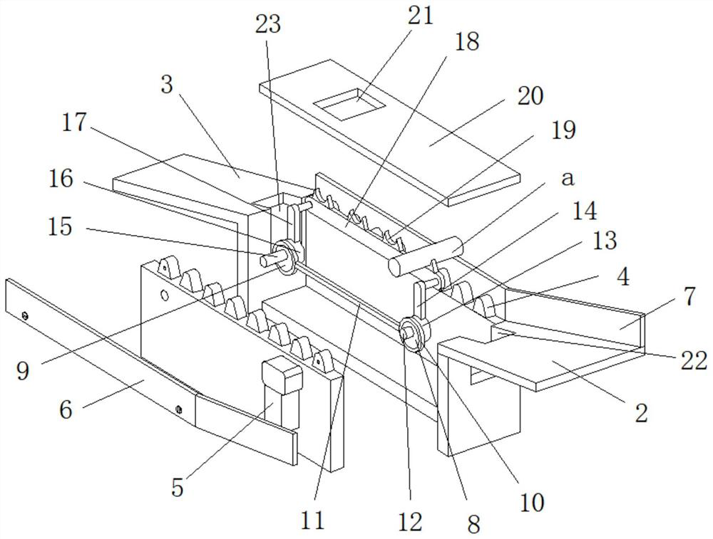
[0013] see figure 1 , the specific embodiment is realized by adopting the following technical scheme, which includes a delivery box 1, the delivery box 1 as a whole is a cuboid structure with an opening on the upper surface, and a positioning delivery device is arranged in the delivery box 1, so The two ends of the conveying box 1 are respectively welded and fixed with a feed plate 2 and a discharge plate 3, and the two sides at the top surface of the conveying box 1 are provided with positioning teeth 4 for positioning the paper tube a, and the conveying box 1 The drive motor assembly 5 used to drive the operation of the positioning conve...


PUM


Abstract

The invention discloses a paper tube conveyor, which comprises a conveying box (1); the whole conveying box (1) is of a cuboid structure with an opening formed in the upper top face; a positioning conveying device is arranged in the conveying box (1); a feeding plate (2) and a discharging plate (3) are fixedly welded to the two ends of the conveying box (1) respectively; positioning teeth (4) used for positioning paper tubes (a) are arranged on the two sides of the upper top face of the conveying box (1); a driving motor assembly (5) used for driving the positioning conveying device to operate is installed on the outer side face of the conveying box (1); and first side plates (6) fixedly welded to the upper top face of the conveying box (1) are arranged on the outer side faces of the positioning teeth (4). On the premise that the conveying effect is not affected, the paper tubes in the conveying box can be conveyed to pass through a window in the conveying process, and then the purpose of fixed-point spraying can be achieved through spray printing equipment.

Description

technical field [0001] The present invention relates to the technical field of manufacturing equipment related to paper products, in particular to a paper tube conveyor. Background technique [0002] At present, most of the conveying methods for the produced and cut paper tubes are driven by plate chains or conveyor belts. At present, for some anti-counterfeiting, production date and brand logo spraying needs, it needs to be manually transferred to spray printing. The main reason for further processing in the operating area is that the paper tubes conveyed by chains or conveyor belts cannot provide a fixed position for the printing equipment. Contents of the invention [0003] The object of the present invention is to provide a paper tube conveyor, which can effectively solve the problems in the background technology. [0004] In order to solve the existing problems in the background technology, it includes a delivery box 1, which is a cuboid structure with an opening on ...

Claims


Application Information

Patent Timeline
IPC IPC(8): B41J3/407B65G47/28B65G47/74
CPCB41J3/40733B65G47/28B65G47/74
Inventor 毛海玉
Owner 安畑生物科技江苏有限公司
Why Eureka
Try Eureka