Waste gas treatment device used in production of adhesive with food protein as raw material
A waste gas treatment device and waste gas treatment technology, which are applied in the separation of dispersed particles, chemical instruments and methods, separation methods, etc., can solve the problems of inability to adjust the spray amount of spray liquid, waste gas treatment effect of spray liquid, etc. Waste gas treatment effect, avoid spray liquid waste, improve safety effect
- Summary
- Abstract
- Description
- Claims
- Application Information
AI Technical Summary
Problems solved by technology
Method used
Image
Examples
Embodiment 1
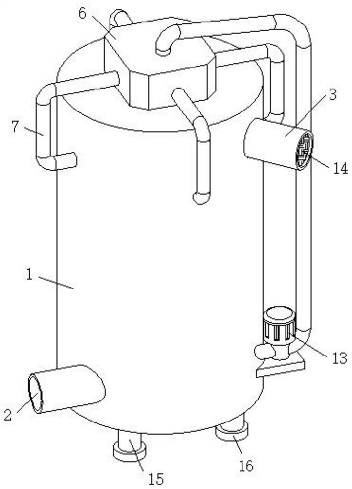
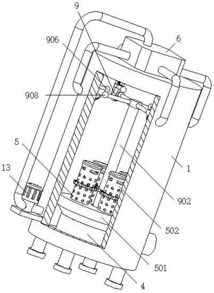
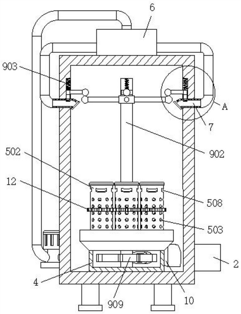
[0034] refer to Figure 1-6 , a waste gas treatment device for producing adhesives with food protein as raw material, comprising a waste gas treatment tank 1, the lower end and the upper end of the waste gas treatment tank 1 are fixedly connected with an air inlet pipe 2 and an air outlet pipe 3 respectively, and the inside of the waste gas treatment tank 1 A fixed cylinder 4 is fixedly installed on the bottom wall, and the top of the fixed cylinder 4 is fixedly installed with an exhaust gas diversion mechanism 5 for making the exhaust gas distribution inside the exhaust gas treatment tank 1 more uniform. The liquid storage tank 6, the side wall of the liquid storage tank 6 is fixedly connected with a number of spray pipes 7, and each spray pipe 7 is fixedly connected with a telescopic hose 8 on the part extending to the inside of the exhaust gas treatment tank 1, and the telescopic The inside of the hose 8 is equipped with a spray volume adjustment mechanism 9 for automatical...
Embodiment 2
[0039] Such as Figure 6 As shown, this embodiment is basically the same as Embodiment 1. Preferably, the exhaust gas diversion mechanism 5 includes a cover plate 501 fixedly installed on the top of the fixed cylinder 4, and the top of the cover plate 501 is connected to several splitter cylinders 502 through bearings, each The side walls of each splitter tube 502 are provided with evenly distributed splitter holes 503, and the inner top wall of each splitter tube 502 is fixedly equipped with a pressure relief piece, the pressure relief piece includes a circular tube 504, each circular The inside of cylinder 504 is all slidably equipped with movable rod 505, is all fixedly connected with constant pressure spring 506 between the top of each movable rod 505 and the inner top wall of corresponding circular cylinder 504, and the bottom of each movable rod 505 is all fixed. A piston plate 507 is connected, and the upper end of the peripheral wall of each splitter cylinder 502 is pr...
Embodiment 3
[0042] Such as image 3 and Figure 5 As shown, this embodiment is basically the same as Embodiment 1. Preferably, a transmission gear 11 is fixedly installed on the peripheral wall of the rotating rod 902, and a gear meshing with the transmission gear 11 is fixedly installed on the outer wall of each splitter tube 502. Ring 12.
[0043] In this embodiment, the rotating rod 902 drives the transmission gear 11 to rotate and makes it drive the gear ring 12 to rotate, and the rotation of the gear ring 12 drives the shunt tube 502 to rotate, so that the air flow distribution inside the exhaust gas treatment tank 1 is more uniform, and the exhaust gas purification is improved. Effect.
PUM
 Abstract
Description
Claims
Application Information
 - R&D Engineer
- R&D Manager
- IP Professional
- Industry Leading Data Capabilities
- Powerful AI technology
- Patent DNA Extraction
Browse by: Latest US Patents, China's latest patents, Technical Efficacy Thesaurus, Application Domain, Technology Topic, Popular Technical Reports.
© 2024 PatSnap. All rights reserved.Legal|Privacy policy|Modern Slavery Act Transparency Statement|Sitemap|About US| Contact US: help@patsnap.com


