
Wheel set type load reducing device

A technology of a load-reducing device and a wheel set, which is applied in travel or camping equipment, travel bags, household appliances, etc., and can solve problems such as the inability to further reduce human metabolic consumption, the inability to adapt to walking speed and load quality, and the reduction of load acceleration and overturning moments. , to achieve the effect of reducing the risk of scoliosis, reducing the risk of injury, and reducing energy consumption

Active Publication Date: 2021-11-05
HUAZHONG UNIV OF SCI & TECH
View PDF13 Cites 0 Cited by
  • Summary
  • Abstract
  • Description
  • Claims
  • Application Information

AI Technical Summary

Problems solved by technology

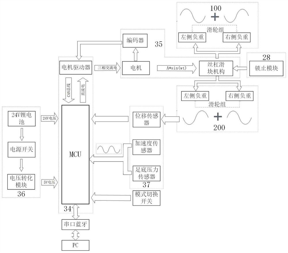
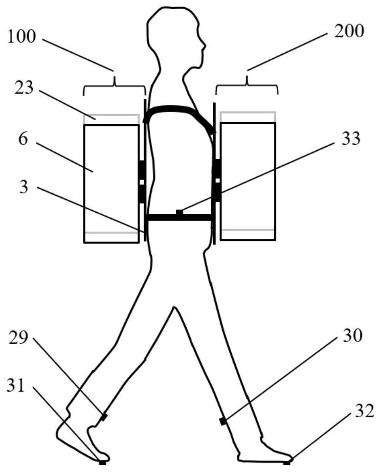
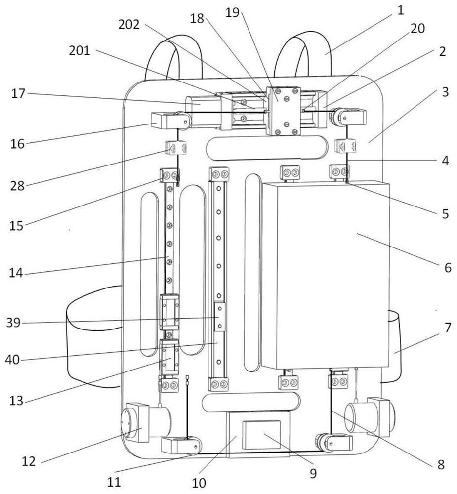
[0006] Aiming at the above defects or improvement needs of the prior art, the present invention provides a wheel-type load-reducing device, which is composed of two backpacks respectively fixed on the chest and back of the human body, and the front and rear backpacks can approximately evenly load the On both sides of the coronal plane and sagittal plane of the human body, the front and rear backpacks drive the screw slider mechanism through two synchronous motors, and then the pulley assembly makes the load move in antiphase on the coronal plane of the front and rear backpacks, reducing the acceleration of human walking load and the load on the coronal plane. The overturning moment with the sagittal plane reduces the consumption of human metabolism and enhances the lateral stability of the human body. It solves the problem that the existing suspended backpacks are large in size and cannot adapt to different walking speeds and load masses, which will reduce the lateral stability of the human body and cannot further reduce human metabolism. Consumption and other issues

Method used


Image

  • Wheel set type load reducing device
  • Wheel set type load reducing device
  • Wheel set type load reducing device

Examples


Embodiment Construction

[0045] In order to make the object, technical solution and advantages of the present invention clearer, the present invention will be further described in detail below in conjunction with the accompanying drawings and embodiments. It should be understood that the specific embodiments described here are only used to explain the present invention, not to limit the present invention. In addition, the technical features involved in the various embodiments of the present invention described below can be combined with each other as long as they do not constitute a conflict with each other.

[0046] In describing the present invention, it is to be understood that the terms "central", "lateral", "upper", "lower", "front", "rear", "left", "right", "vertical" , "horizontal", "bottom", "inner", "outer" and other indicated orientations or positional relationships are based on the orientations or positional relationships shown in the drawings, and are only for the convenience of describing...


PUM


Abstract

The invention discloses a wheel set type load reducing device, which belongs to the technical field of power knapsacks, and comprises a first knapsack and a second knapsack which have the same structure and are fixed on the front side and the rear side of a human body, the first backpack comprises a first load, a second load, a sliding assembly, a motion output unit, a motion control unit and a data acquisition unit; the data acquisition unit acquires motion information of the center of mass of a human body and transmits the motion information to the motion control unit, and the motion control unit is used for controlling the motor to drive the lead screw sliding block mechanism to pull the first steel wire rope according to the motion information so that the first load and the second load can oppositely move along the sliding assembly, therefore, the movement amplitude of the first load and the second load is the same as the up-down movement amplitude in the human body movement process, and the movement frequency is 1 / 2 of the human body movement frequency. The lateral stability of a human body during weight-bearing walking is enhanced, and the injury risk in the weight-bearing walking process is reduced.

Description

technical field [0001] The invention belongs to the technical field of power backpacks, and more specifically relates to a wheel set type load-reducing device. Background technique [0002] Walking with a load is a common activity in human life. For combat soldiers, the average load is 53 kg, and the injury caused by the load is four times that of the combat injury. It will also lead to a decline in battlefield performance and even threaten their survival. For backpackers, students and other groups, the load also tends to exceed 15% of the weight of the bearer. Walking with a heavy load will greatly increase metabolic consumption, easily cause fatigue, and reduce combat capability. In addition, walking with a heavy load will also generate an acceleration force that is 2 to 3 times greater than gravity, which can easily lead to lumbar spine, muscle, joint damage and shoulder tissue contusion. . Therefore, it is of great significance to reduce the consumption of metabolic en...

Claims


Application Information

Patent Timeline
Patent Type & Authority Applications(China)
IPC IPC(8): A45F3/10A45C15/00
CPCA45F3/10A45C15/00
Inventor 梁杰俊一汪涛刘阳孙晨露熊蔡华
Owner HUAZHONG UNIV OF SCI & TECH
Learn More