
A network optical fiber defect detection device and method

A technology of defect detection and optical fiber, which is applied in the direction of measuring devices, optical instrument testing, testing optical fiber/optical waveguide equipment, etc., can solve the problems of poor adjustable effect, insufficient tension of optical fiber lines, and optical fiber loss, etc. sexual effect

Active Publication Date: 2022-05-03
深圳市南方联合科技有限公司
View PDF17 Cites 0 Cited by
  • Summary
  • Abstract
  • Description
  • Claims
  • Application Information

AI Technical Summary

Problems solved by technology

[0005] In order to solve the above technical problems, the present invention provides a network optical fiber defect detection device and method to solve the problem that the existing similar adjustable effects are poor, and it is impossible to conveniently detect the passability of optical fibers and the detection of end-face defects, and the defects of optical fiber interfaces and end faces. Unclean and the end face of the fiber optic connector is not parallel to the end face of the fiber cleaning pen, which may easily cause fiber defects and lead to fiber loss. Its bending and breaking cause fiber loss, or when the fiber is being measured, the tension of the fiber cable at the measurement end is insufficient, resulting in inaccurate measurement

Method used


Image

  • A network optical fiber defect detection device and method
  • A network optical fiber defect detection device and method
  • A network optical fiber defect detection device and method

Examples


no. 1 example

[0043] as attached figure 1 To attach Figure 9 Shown:

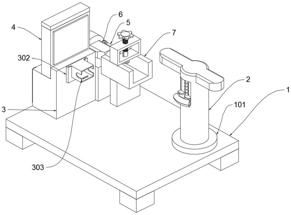
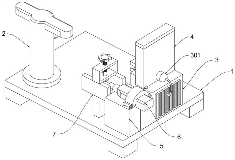
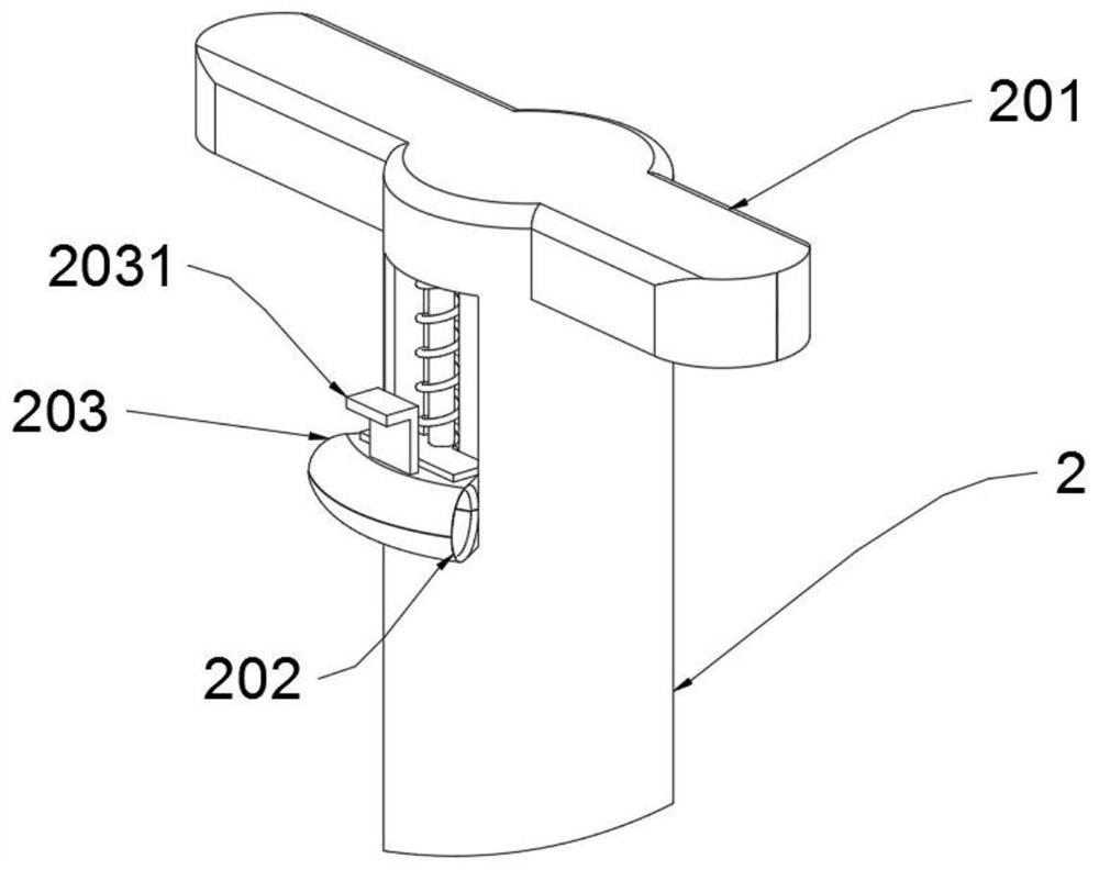
[0044] The invention provides a network optical fiber defect detection device and method, comprising a base frame 1, a controller is provided on one side of the base frame 1, the controller electrically controls each electrical component, and a rotating seat 101 is provided on the top of the base frame 1, The top of the seat 101 is provided with a wire column 2, the left end of the base frame 1 is provided with a device main body 3, and the left end of the base frame 1 is slidably connected to an installation device 5, and an optical fiber cleaning pen 6 is provided on the installation device 5;

[0045] The main body 3 of the device is provided with an installation tank 302, and the inside of the installation tank 302 is provided with a plug joint 303, and the top of the main body 3 of the device is connected with a display 4;

[0046] The front end of the mounting device 5 is provided with a fixing device 7 .

[004...

no. 2 example

[0062]Based on the network optical fiber defect detection device and method provided in the first embodiment, the depth of the optical fiber connector plugged into the plug connector 303 needs to be manually regulated in actual use, so it is inevitable that the optical fiber connector will be squeezed and damaged due to excessive force , or too little force leads to inaccurate detection. At the same time, when the wire post 2 is rotated to tighten the optical fiber, the degree of tension cannot be precisely controlled, so not only will it cause damage to the optical fiber, but it will also damage the optical fiber connector Cleanliness detection results are affected; at the same time, when the optical connector is cleaned, the optical fiber cleaning pen 6 is driven by the installation device 5 to move to the end of the optical fiber connector to clean it, so the fixed position of the optical fiber connector in the fixing device 7 and The traveling distance of the optical fiber ...


PUM


Abstract

The invention provides a network optical fiber defect detection device and method, which relate to the technical field of optical fiber detection and include a base frame, a controller is provided on one side of the base frame, a rotating seat is provided on the top of the base frame, and the rotating The top of the seat is provided with a wire column, and the outer surface of the wire column is provided with a fastening device; the top side of the base frame is provided with a device body, and the device body is provided with a launch unit, and the top side of the base frame is An electric telescopic rod is provided, the output end of the electric telescopic rod is provided with an installation device, and an optical fiber cleaning pen is provided inside the installation device; an installation tank is provided on the main body of the device, and a As for the plug joint, the installation groove body is a concave block and a card slot is opened on the upper end. The invention is convenient for detecting and cleaning the optical fiber, ensures the detection accuracy of the feeding depth during the detection and cleaning, and avoids the loss of the optical fiber caused by the defect of the optical fiber caused by the end face of the optical fiber connector being not parallel to the end face of the optical fiber cleaning pen.

Description

technical field [0001] The invention belongs to the technical field of optical fiber detection, and more specifically relates to a network optical fiber defect detection device and method. Background technique [0002] Various defects occur during the drawing of the fiber from the blank; these defects include holes in the fiber, impurities or particles in the fiber, particles on the surface of the fiber, and surface abrasions; The first process stage causes fiber breakage. [0003] A network optical fiber defect detection device and method can refer to the Chinese invention patent application number CN201310045412.2, which mainly includes a reflective optical fiber sensor probe, an 820nm optical transmitter, a photoelectric converter, a signal processing integrated circuit board, and a PC; 820nm The optical transmitter can provide a light source for the reflective fiber optic sensor probe. The photoelectric converter receives 820nm light and converts it into an analog volta...

Claims


Application Information

Patent Timeline
Patent Type & Authority Patents(China)
IPC IPC(8): G01M11/00
CPCG01M11/30
Inventor 杨林
Owner 深圳市南方联合科技有限公司
Learn More