Sliding type air inlet ventilation mechanism of airplane auxiliary power unit

An aircraft auxiliary power and sliding technology, which is applied in the direction of auxiliary power equipment, aircraft parts, air handling equipment, etc., can solve the problems of difficult layout and structure installation, large air intake, and large power of aircraft auxiliary power devices. , to achieve the effect of flexible arrangement position and method, large opening area, flexible actuator selection and arrangement method

Active Publication Date: 2021-11-02
COMAC +1
View PDF4 Cites 0 Cited by
  • Summary
  • Abstract
  • Description
  • Claims
  • Application Information

AI Technical Summary

Problems solved by technology

In addition, in the design of some large-scale civil aircraft, the power of the auxiliary power unit of the aircraft is large, the air intake volume is large, and the area of ​​the intake valve is also large. At this time, the intake valve actuator 13 must also be selected correspondingly larger. specifications, which caused certain difficulties to its layout and structural installation;
[0007] (2) The push rod 13a of the intake valve actuator 13 is located in the path of the intake air flow, which will cause unnecessary disturbance to the intake air
Especially when the intake valve 11 is opened, the push rod 13a passes through the middle part of the intake duct 14, which has a certain influence on the intake air.

Method used


Image

  • Sliding type air inlet ventilation mechanism of airplane auxiliary power unit
  • Sliding type air inlet ventilation mechanism of airplane auxiliary power unit
  • Sliding type air inlet ventilation mechanism of airplane auxiliary power unit

Examples


Embodiment Construction

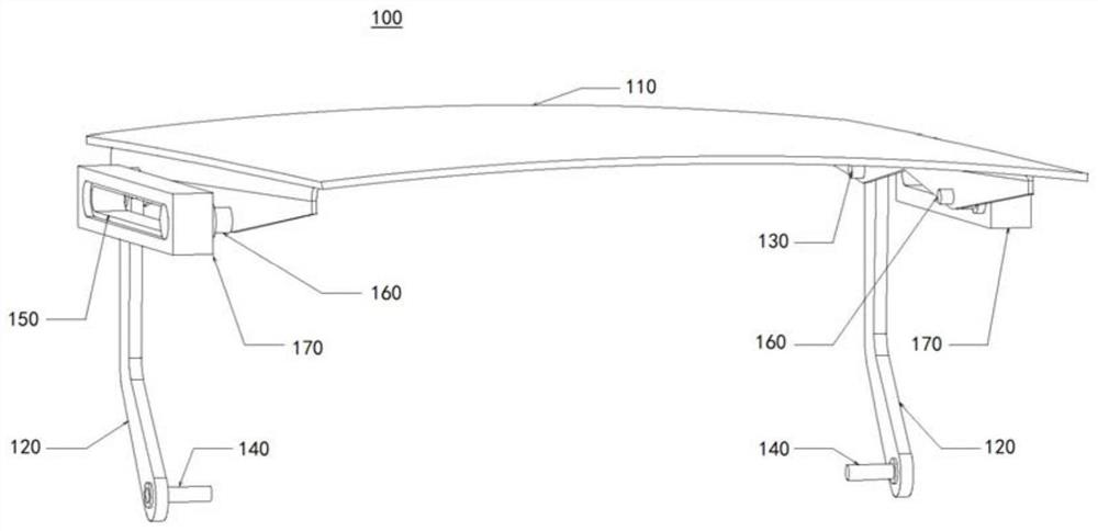
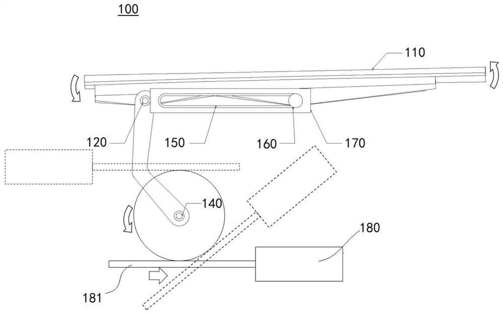
[0047] Below, refer to figure 1 and figure 2 , the sliding air intake ventilation mechanism 100 of the aircraft auxiliary power unit of the present invention will be described in detail. figure 1 It is a perspective view of the composition of the sliding intake ventilation mechanism 100 of an aircraft auxiliary power unit according to an embodiment of the present invention, wherein the driving mechanism (intake valve actuator) included in the sliding intake ventilation mechanism 100 is not shown , figure 2 It is a schematic diagram showing the arrangement of the driving mechanism (intake valve actuator) with respect to the intake valve 110 and the transmission mechanism in the sliding intake ventilation mechanism 100 according to one embodiment of the present invention.

[0048] Such as figure 1 As shown, the sliding intake and ventilation mechanism 100 of the aircraft auxiliary power unit of the present invention includes an intake valve 110 whose curved shape matches...


PUM


Abstract

The invention discloses a sliding type air inlet ventilation mechanism of an airplane auxiliary power unit. Selection and arrangement of an air inlet valve actuator are freer, and air inlet cannot be affected. The sliding type air inlet ventilation mechanism comprises an air inlet valve, a driving mechanism, two sets of transmission mechanisms, an air inlet valve rotating shaft, a driving shaft and two sets of movement limiting mechanisms, the curved surface shape of the air inlet valve is matched with an aircraft fuselage skin, and the air inlet valve is opened or closed through the driving mechanism; the transmission mechanisms are arranged on the two sides of the intake valve in the length direction, the two ends of the transmission mechanisms are connected with the intake valve and the driving mechanism, the end, close to the intake valve, of each transmission mechanism is connected with the intake valve through the corresponding intake valve rotating shaft, and the end, close to the driving mechanism, of each transmission mechanism is connected with the driving mechanism through the corresponding driving shaft. Each movement limiting mechanism is provided on one side and the other side in the longitudinal direction of the intake valve, respectively, on the outer side in the longitudinal direction of the intake valve with respect to the intake valve.

Description

technical field [0001] The invention relates to air intake and ventilation cooling of an aircraft auxiliary power unit, and more particularly relates to a sliding intake ventilation mechanism of an aircraft auxiliary power unit. Background technique [0002] The aircraft auxiliary power unit is mainly used to start the main engine and supply air to the cabin, and provide auxiliary power for various airborne equipment. Usually when the main engine is not working when the aircraft is on the ground, the main air source and power supply come from the auxiliary power unit of the aircraft. The aircraft auxiliary power unit needs to inhale airflow from the outside of the fuselage through the air intake system and ventilation cooling system. The air intake system airflow is used for the operation of the aircraft auxiliary power unit itself, and the ventilation cooling airflow is used for the lubricating oil radiator of the aircraft auxiliary power unit. , aircraft auxiliary power u...

Claims


Application Information

Patent Timeline
IPC IPC(8): B64D13/06B64D41/00
CPCB64D13/06B64D41/00B64D2013/0611B64D2013/0685
Inventor 周成思王晗王栋张发富陈韡蓝天
Owner COMAC
Why Eureka
Try Eureka