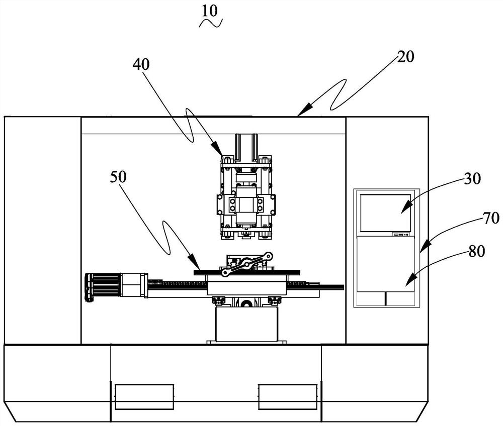
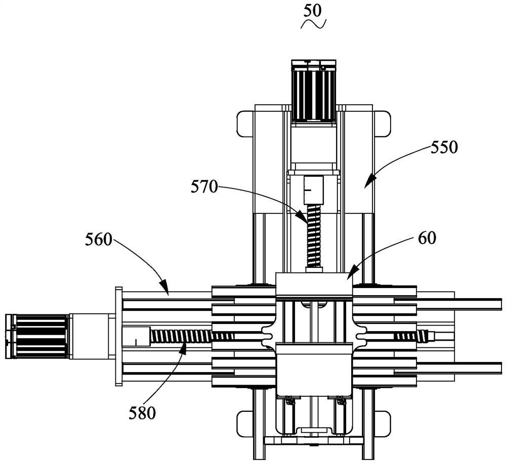
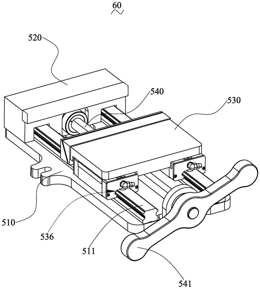
Numerical control machining center with elastic clamping jig

A processing center and clamping technology, applied in metal processing equipment, metal processing machinery parts, clamping, etc., can solve the problems of low processing efficiency, high maintenance cost, short service life of clamping fixtures, etc., and improve processing efficiency , The effect of reducing the processing defect rate

Active Publication Date: 2021-11-02
深圳市锴诚精密模具有限公司
View PDF11 Cites 0 Cited by
  • Summary
  • Abstract
  • Description
  • Claims
  • Application Information

AI Technical Summary

Problems solved by technology

In the existing numerical control processing equipment, when the clamping fixture clamps the workpiece, if the workpiece is clamped too loosely, the workpiece will easily shift during the processing process, resulting in the processed workpiece being unqualified, and the defect rate remains high; Or during the processing, the workpiece falls from the clamping fixture, which affects the processing efficiency of the CNC processing equipment;
[0004] If the clamping fixture clamps the workpiece too tightly, it will easily cause the workpiece to be overstressed and damaged; and excessive clamping force will easily cause the clamping fixture to loosen and shorten the service life of the clamping fixture; That is, if the clamping fixture clamps the workpiece too tightly, frequent repairs and replacement of the clamping fixture are required, resulting in low processing efficiency and high maintenance costs

Method used


Image

  • Numerical control machining center with elastic clamping jig
  • Numerical control machining center with elastic clamping jig
  • Numerical control machining center with elastic clamping jig

Examples


Embodiment Construction

[0036] In order to facilitate understanding of the present invention, the present invention will be further described with reference to the related drawings. The preferred embodiment of the present invention is given in the drawings. However, the present invention can be implemented in many different forms, and is not limited to the embodiments described herein. Conversely, the purpose of providing these embodiments is to make the disclosure of the present invention more thoroughly comprehensively.

[0037] It should be noted that when the element is referred to as "fixed to" another element, it can be directly in another element or may exist in the hidden element. When an element is considered to be "connected" another element, it can be directly connected to another element or may exist at the same time. The term "vertical", "horizontal", "horizontal", "left", "right", and similar expressions are merely illustrative, and the only embodiment is not shown.

[0038] All technical a...


PUM


Abstract

The invention relates to a numerical control machining center with an elastic clamping jig. The numerical control machining center comprises a numerical control machining machine shell, a touch display screen, a control system, the elastic clamping jig and a machining tool bit system. The elastic clamping jig comprises an elastic clamping mechanism, the elastic clamping mechanism comprises a clamping base, a fixed clamping piece, a movable clamping assembly and a clamping loosening and tightening lead screw, the fixed clamping piece is fixedly arranged on the clamping base, and the movable clamping assembly is arranged on the clamping base in a sliding mode; the movable clamping assembly is in driving connection with the clamping loosening and tightening lead screw; and the movable clamping assembly comprises a first movable block, a second movable block and an adjusting spring, and the first movable block and the second movable block are connected through the adjusting spring. According to the numerical control machining center with the elastic clamping jig, a workpiece is elastically clamped, and the situation that the workpiece is stably clamped through elastic clamping, and meanwhile the workpiece cannot be clamped too tightly; and the machining reject ratio of the workpieces is reduced, and the machining efficiency of the workpieces is improved.

Description

Technical field [0001] The present invention relates to the technical field of CNC machining equipment, and more particularly to a CNC machining center having an elastic assembly. Background technique [0002] CNC machining center for processing of workpieces. The CNC machining center has an input system, a control system, an operating system, and the like, and the corresponding control signal is issued to the operating system after the operation of the input system input, and the control system performs corresponding control signals according to the control signal. [0003] When machining the workpiece, the CNC machining center needs to make the workpiece by loading. When the existing CNC machining equipment, when the generner is fitted with the workpiece, if the workpiece is easy to shift during the processing, the workpiece is unqualified, and the bad rate is high; Or during processing, the workpiece falls from the mounting fixture to effect the processing efficiency of the CN...

Claims


Application Information

Patent Timeline
IPC IPC(8): B23Q3/06
CPCB23Q3/067
Inventor 俞国贤
Owner 深圳市锴诚精密模具有限公司
Why Eureka
Try Eureka